Cemented lens centering control method and system and full-automatic cementing equipment

A cemented lens and control method technology, applied in the direction of control, installation, and optics using feedback, can solve the problems of not being able to ensure the coaxiality of the spherical centers of the three surfaces of the cemented lens, reduce the accuracy of the cemented centering, and improve the cemented centering Accuracy, improved centering efficiency, and improved accuracy

Pending Publication Date: 2020-06-26
XIAN OPTICAL METROLOGY TECH
View PDF7 Cites 4 Cited by
  • Summary
  • Abstract
  • Description
  • Claims
  • Application Information

AI Technical Summary

Problems solved by technology

[0004] To sum up, the problems existing in the existing technology are: in the prior art, the coaxiality of the spherical centers of the three faces of the gluing mirror cannot be guaranteed, and the accuracy of the measurement system can only be graded due to limitations, which reduces the centering accuracy of the gluing

Method used


Image

  • Cemented lens centering control method and system and full-automatic cementing equipment
  • Cemented lens centering control method and system and full-automatic cementing equipment
  • Cemented lens centering control method and system and full-automatic cementing equipment

Examples


Embodiment Construction

[0025] In order to make the object, technical solution and advantages of the present invention more clear, the present invention will be further described in detail below in conjunction with the examples. It should be understood that the specific embodiments described here are only used to explain the present invention, not to limit the present invention.

[0026] Aiming at the problems existing in the prior art, the present invention provides a cemented lens centering control method, system, and automatic gluing equipment. The present invention will be described in detail below with reference to the accompanying drawings.

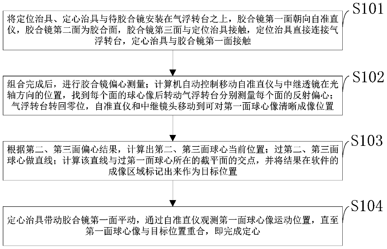
[0027] Such as figure 1 As shown, the cemented lens centering control method provided by the embodiment of the present invention includes:

[0028] S101: Install the positioning jig, centering jig, and gluing mirror on the air-floating turntable, the first side of the gluing mirror faces the autocollimator, the second side of the gluing mirror is the glui...


PUM


Abstract

The invention, which belongs to the technical field of optical adjustment detection, discloses a cemented lens centering control method and system and full-automatic cementing equipment. A positioningjig, a centering jig and a to-be-cemented lens are installed on an air floating rotary table, the first surface of the cemented lens faces an autocollimator, the positioning jig is directly connectedwith the air floating rotary table, and the centering jig makes contact with the first face of the cemented lens; after the combination is finished, eccentricity measurement of the cemented lens is performed; a computer automatically controls the positions of the mobile autocollimator and a relay lens in the optical axis direction, finds the spherical center image of each surface, and then rotates the air floating rotary table to measure the reflection eccentricity of each surface; current positions of sphere centers of the second and third surfaces are calculated according to eccentric results of the second and third surfaces, and a straight line is made through the sphere centers; and the centering jig drives the first surface of the cemented lens to translate, the motion position of the first surface spherical center image is observed through the autocollimator until the first surface spherical center image coincides with the target position, and then centering is completed. The cementing centering precision is improved, and no technical requirement is needed for operators.

Description

technical field [0001] The invention belongs to the technical field of optical assembly and adjustment detection, and in particular relates to a cemented lens centering control method, system and fully automatic cementing equipment. Background technique [0002] At present, the commonly used centering of cemented lenses adopts the method of centering the focus of the transmitted image. The focus centering of the transmitted image locates the optical axis of the gluing mirror by positioning the normalized part with high precision and the target reticle of the calibration position. When gluing, first place the normalized part in the equipment positioning fixture, and move the reticle or Measure the lens so that the focus image cross target coincides with the reticle center plate, and then place the gluing mirror on the positioning fixture, observe the difference between the focus image position of the gluing mirror and the center of the reticle, and perform centering by manual...

Claims


Application Information

Patent Timeline
Patent Type & Authority Applications(China)
IPC IPC(8): G05D3/12G01B11/27G02B7/02
CPCG05D3/12G01B11/27G02B7/025
Inventor 高文姚俊王永锋尹雷
Owner XIAN OPTICAL METROLOGY TECH
Why Eureka
Try Eureka