
Convenient-to-use electric bicycle charger

A technology for electric bicycles and chargers, which is applied to electric vehicles, current collectors, battery circuit devices, etc., can solve the problems of inconvenience, affect the storage effect of electric vehicles, and limited storage space, and achieve the effect of avoiding shock damage.

Inactive Publication Date: 2020-06-26
JIANGXI SHENGLING TECH
View PDF0 Cites 0 Cited by
  • Summary
  • Abstract
  • Description
  • Claims
  • Application Information

AI Technical Summary

Problems solved by technology

[0003] Many users like to carry the charger with the car, and put the charger in the storage box of the electric car. Although it can achieve the effect of charging at any time, it will also bring some problems. There are many components inside the electric car charger. When the car is carried, when encountering obstacles or uneven roads, due to the vibration of the body, it is easy to cause the components in the charger to fall off and be damaged. In this case, continuing to charge will pose a safety hazard. However, electric The storage space of the car itself is limited. If a protective device such as a cushion is placed in the storage box, it will greatly affect the storage effect of the electric car, and it will be inconvenient for people to use.

Method used


Image

  • Convenient-to-use electric bicycle charger
  • Convenient-to-use electric bicycle charger
  • Convenient-to-use electric bicycle charger

Examples


Embodiment

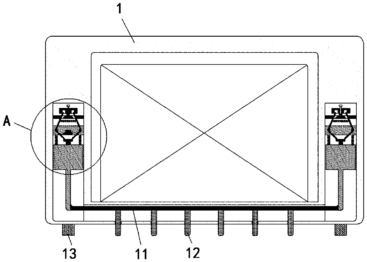
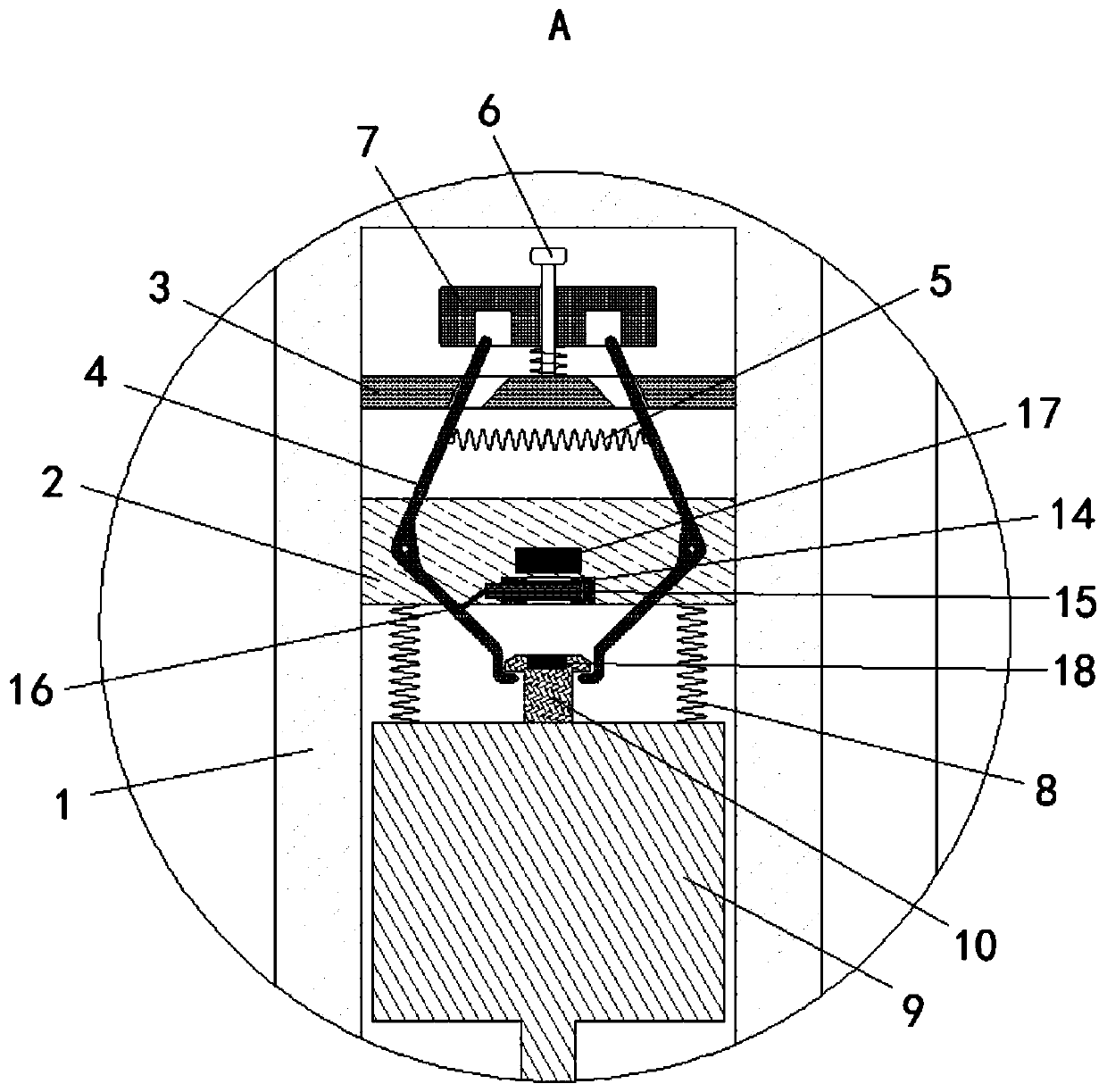
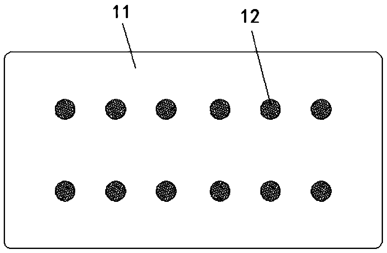
[0028] as attached figure 1 to attach image 3 Shown:

[0029] The present invention provides a convenient electric bicycle charger, comprising a casing 1, a support plate 2 is fixedly connected to the side wall of the casing 1, a top plate 3 is fixedly connected to the inside of the casing 1 and above the support plate 2, and the support plate 2 A support assembly 4 extending to the top of the top plate 3 is movably installed on the front of the top plate 3, a guide rod 6 is fixedly connected to the top of the top plate 3, and a drive plate 7 is movably socketed on the outside of the guide rod 6, and the bottom of the support plate 2 is installed with a pressure spring 8 The lifting plate 9, the top of the lifting plate 9 is fixedly connected with the clamping plate 10 corresponding to the clamping assembly 4, the bottom of the lifting plate 9 is fixedly connected with a push plate 11, and the bottom of the push plate 11 is fixedly installed with a The elastic rod 12 of the...


PUM


Abstract

The invention provides a convenient-to-use electric bicycle charger. The charger comprises a shell. Clamping assemblies extending to the positions above top plates are movably installed on the front faces of supporting plates. Driving plates are movably mounted at the tops of the top plates through guide rods. Lifting plates are mounted at the bottoms of the supporting plates through pressure springs. Elastic rods are fixedly mounted at the bottom of a push plate. Foot pads are fixedly mounted at the bottom of the shell. Barrier plates are movably inserted into isolation seats. Magnetic blocksI are fixedly connected above the isolation seats, and magnetic blocks II are fixedly connected to the tops of clamping plates. When an electric vehicle bumps, the shell is subjected to an upward inertia impact force, the driving plates and the top plates relatively move, the driving plates extrude the clamping assemblies to enable the clamping assemblies to rotate to loosen the clamping plates,the barrier plates move, the lifting plates are pushed by the repulsive force between the pressure springs and the magnetic blocks to move downwards to drive the elastic rods to extend downwards, andwhen the shell falls, the elastic rods play a role in buffering and protecting, so that components in the charger can be effectively protected from being damaged.

Description

technical field [0001] The invention belongs to the technical field of electric vehicle chargers, in particular to a convenient electric bicycle charger. Background technique [0002] There are a large number of electric bicycles in our country. On some narrow roads or when the travel distance is short, the mobility and flexibility of electric bicycles are far better than those of cars. Therefore, many families choose electric bicycles as a means of transportation. Electric bicycles With the battery as the power source, the remaining power of the battery is directly related to the driving distance of the electric bicycle. Therefore, in order to ensure the normal travel of people's daily life, after using the electric bicycle, it is necessary to charge the battery in time. [0003] Many users like to carry the charger with the car, and put the charger in the storage box of the electric car. Although it can achieve the effect of charging at any time, it will also bring some pr...

Claims


Application Information

Patent Timeline
Patent Type & Authority Applications(China)
IPC IPC(8): H02J7/00F16F15/03F16F15/04
CPCF16F15/03F16F15/04H02J7/0042
Inventor 吴世伟
Owner JIANGXI SHENGLING TECH
Learn More