Occlusion mechanism and occlusion method after bending of coil leading-out wire end

A technology for lead-out wires and wire ends, which is used in electromechanical devices, manufacturing motor generators, electrical components, etc., and can solve problems such as being unable to adapt to automated production operations.

Pending Publication Date: 2020-06-26
SHANXI FENXI HEAVY IND
View PDF0 Cites 2 Cited by
  • Summary
  • Abstract
  • Description
  • Claims
  • Application Information

AI Technical Summary

Problems solved by technology

[0004] The invention provides a occlusal mechanism and occlusal method after coil lead-out wire ends are bent, which solves the technical problem that the prior art cannot be adapted to the automatic production flow operation

Method used


Image

  • Occlusion mechanism and occlusion method after bending of coil leading-out wire end
  • Occlusion mechanism and occlusion method after bending of coil leading-out wire end
  • Occlusion mechanism and occlusion method after bending of coil leading-out wire end

Examples


Embodiment Construction

[0027] The present invention is described in detail below in conjunction with accompanying drawing:

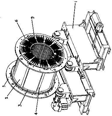
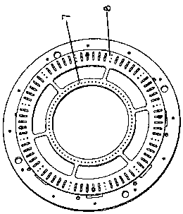
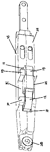
[0028] A occlusal mechanism after the lead-out wire end of a coil is bent, including a servo roller bracket 1, on which a stator core 2 is movably arranged, and the stator core 2 is movably erected on the servo roller bracket through tooling rings 5 ​​on both sides 1, the tooling ring 5 is connected with a double-ring support plate 6 for installing lead line positioning and bending tooling, and a butt joint is arranged between the inner ring plate 7 and the outer ring plate 8 of the double-ring support plate 6. Together with the positioning strip 9, in the positioning piercing hole 10 of the inner ring lead-out line on the positioning strip 9, the inner ring lead-out line is passed through the bending thread head 12, and the outer ring on the positioning strip 9 is drawn out In the line positioning piercing hole 11, the outer ring lead-out line is pierced with a bent thread en...


PUM


Abstract

The invention discloses an occlusion mechanism and an occlusion method after the bending of a coil leading-out wire end, and solves the technical problem that the prior art cannot adapt to automatic production line production. Shearing the thread ends of the inner ring leading-out wires according to the splicing length, and bending outwards through an inner ring leading-out wire bending table to obtain inner ring leading-out wire bending thread ends (12); shearing the wire end of the outer ring leading-out wire according to the splicing length, and bending inwards through an outer ring leading-out wire bending table to obtain an outer ring leading-out wire bending wire end (13); a C-shaped connecting clamp (24) is buckled between the inner ring leading-out wire bending head (12) and the outer ring leading-out wire bending head (13); the jaw (23) is moved to the C-shaped connecting clamp (24), the bayonet of the C-shaped connecting clamp (24) is closed by operating the electric controloil cylinder (16), and the inner ring leading-out wire bending wire head (12) and the outer ring leading-out wire bending wire head (13) are kneaded together. And conditions are provided for production automation.

Description

technical field [0001] The invention relates to a connection mechanism of a coil joint, in particular to a mechanism and a method for engaging the wire ends of the inner coil and the outer coil of the coil through a pliers on an automatic production line after the stator core of the generator is embedded. Background technique [0002] Marine generators are used in ship power systems and are important supporting equipment for ship power systems. Among them, 3MW and 5MW have a large demand and need to be mass-produced; this type of electronic core is made of selenium steel sheet after stamping It is formed by lamination. Positioning rings are arranged at both ends of the cylindrical laminated iron core, and ribs are arranged at equal intervals on the outer surface of the cylindrical iron core. The two positioning rings and the ribs arranged at intervals form the stator core. In the inner side of the stator core, a coil embedding slot is provided, and the copper flat wire coil ...

Claims


Application Information

Patent Timeline
Patent Type & Authority Applications(China)
IPC IPC(8): H02K15/00
CPCH02K15/0068
Inventor 毕晋燕李利民丁卫刚李秋燕
Owner SHANXI FENXI HEAVY IND
Why Eureka
Try Eureka