Large-scale MIMO transmission method and device
A multi-antenna transmission, wireless signal technology, applied in the field of wireless communication, can solve the problem of low transmission power of a single antenna, and achieve the effect of improving the receiving performance
- Summary
- Abstract
- Description
- Claims
- Application Information
AI Technical Summary
Problems solved by technology
Method used
Image

Examples
Embodiment 1
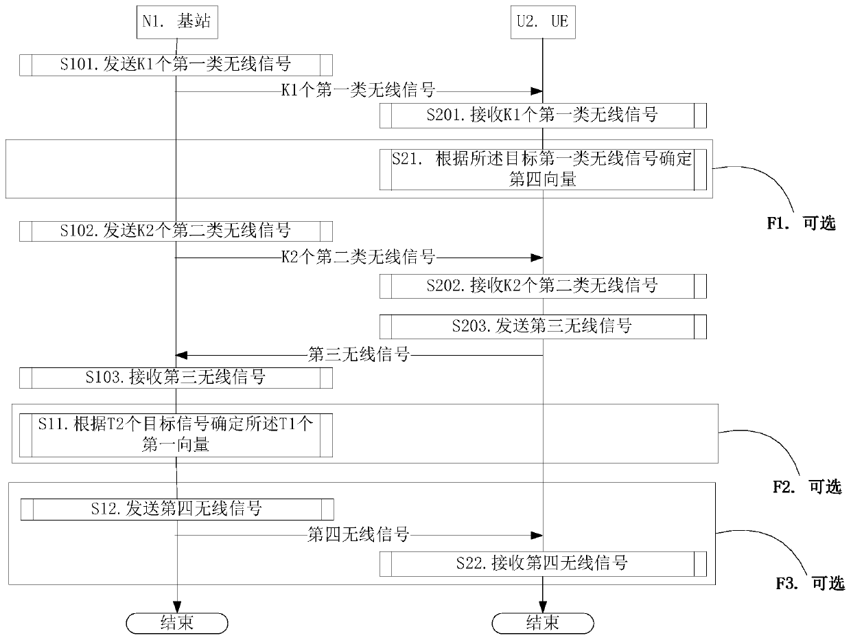
[0152] Embodiment 1 illustrates the flow chart of wireless transmission, as attached figure 1 shown. attached figure 1In , the base station N1 is the serving cell maintenance base station of the UE U2. attached figure 1 , the steps in box F1, box F2 and box F3 are optional.
[0153] For N1, send K1 first-type wireless signals in step S101; send K2 second-type wireless signals in step S102; receive the third wireless signal in step S103; determine the target signal according to T2 in step S11 The T1 first vectors, the T2 target signals are respectively sent by T2 terminals, the UE U2 is one of the T2 terminals, and the third wireless signal is one of the T2 target signals . The T2 is a positive integer, and one target signal is used to determine T second-type RS resources in one second-type radio signal; in step S12, a fourth radio signal is sent.
[0154] For U2, receive K1 first-type wireless signals in step S201; determine a fourth vector according to the target first-...
Embodiment 2
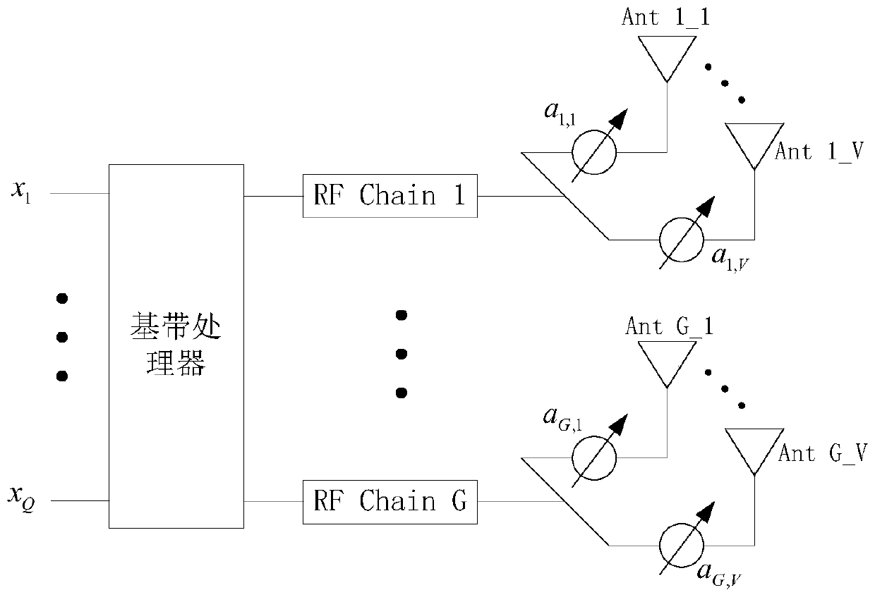
[0163] Embodiment 2 illustrates the schematic diagram of the antenna structure, as attached figure 2 shown. attached figure 2 In this example, the communication node is equipped with G antenna groups, and the G antenna groups correspond to G RF (Radio Frequency, radio frequency) Chains (chains) respectively. One antenna group includes V antennas, G is a positive integer, and V is a positive integer. For 1≤g≤G, the antennas in antenna group #g include the attached figure 2 In {Ant g_1,Ant g_2,...,Ant g_V}, the antenna {Ant g_1,Ant g_2,...,Ant g_V} passes the beamforming vector [a g,1 a g,2 …a g,V ] for analog beamforming.
[0164] As a sub-embodiment 1 of Embodiment 2, the communication node is a base station, and figure 2 x in 1 ,...x Q is the useful signal to be sent, and the useful signal is sent after undergoing digital beamforming and analog beamforming. The baseband processor is used for the x 1 ,...x Q perform digital beamforming, the [a g,1 a g,2 …...
Embodiment 3
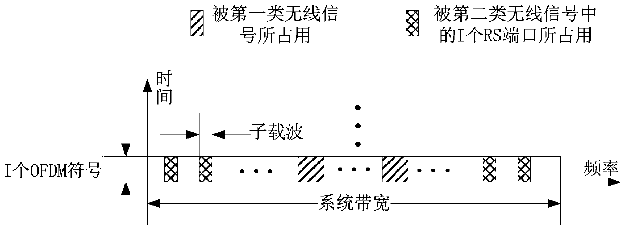
[0179] Embodiment 3 illustrates a schematic diagram of resource mapping of RS ports in the first type of wireless signal and the second type of wireless signal, as shown in the attached image 3 shown. attached image 3 In , the slash marks the time-frequency resource occupied by the first type of wireless signal in one OFDM symbol, and the cross line marks the time-frequency resource occupied by one RS port of the second type of wireless signal in one OFDM symbol resources, the i is a positive integer.
[0180] As a sub-embodiment 1 of Embodiment 3, any RU (Resource Unit, resource unit) in the one OFDM symbol is used by one of {the first type of wireless signal, the second type of wireless signal} occupy. The RU occupies the bandwidth of one subcarrier in the frequency domain, and occupies the duration of one OFDM symbol in the time domain.
[0181] As a sub-embodiment 2 of Embodiment 3, the one OFDM symbol can only be occupied by one wireless signal of the first type, an...
PUM
 Abstract
Description
Claims
Application Information
 - R&D
- Intellectual Property
- Life Sciences
- Materials
- Tech Scout
- Unparalleled Data Quality
- Higher Quality Content
- 60% Fewer Hallucinations
Browse by: Latest US Patents, China's latest patents, Technical Efficacy Thesaurus, Application Domain, Technology Topic, Popular Technical Reports.
© 2025 PatSnap. All rights reserved.Legal|Privacy policy|Modern Slavery Act Transparency Statement|Sitemap|About US| Contact US: help@patsnap.com