Active control type air valve plate

A technology of active control and air valve, which is applied in the direction of motor vehicles, electric vehicles, climate sustainability, etc., can solve real-time adjustment, cannot realize pantograph and catenary, and cannot realize pantograph control unit real-time control of gas path Monitoring and other issues to achieve real-time monitoring and improve the quality of flow

Pending Publication Date: 2020-06-30
株洲万新轨道电气科技有限公司
View PDF0 Cites 1 Cited by
  • Summary
  • Abstract
  • Description
  • Claims
  • Application Information

AI Technical Summary

Problems solved by technology

[0003] The stability of the current quality of high-speed EMUs depends on the dynamic pressure of the pantograph and the catenary, and the dynamic pressure requirements vary at different speed levels, especially for high-speed pantographs with a speed level of ≥300km / h. However, The existing pantograph air valve plate cannot realize the real-time adjustment of the average dynamic pressure of the pantograph and catenary, nor can it realize the real-time monitoring of the gas circuit by the pantograph control unit

Method used


Image

  • Active control type air valve plate
  • Active control type air valve plate
  • Active control type air valve plate

Examples


Embodiment

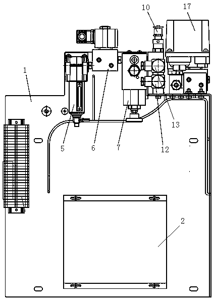
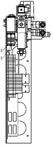
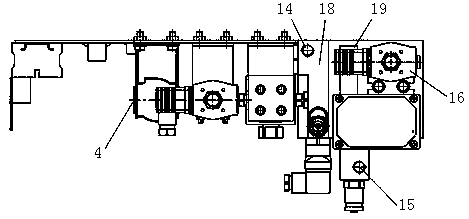
[0023] Referring to the accompanying drawings, this embodiment includes a bottom plate 1 on which a control unit 2 and an air circuit unit 3 are installed. The air circuit unit 3 includes an air inlet 4, a filter valve 5, a bow solenoid valve 6, a Precision pressure regulating valve 7, high frequency valve I8, high frequency valve II9, safety valve 10, pressure sensor I12, pressure sensor II13, air outlet 14, feedback port 15, electromagnetic quick discharge valve 16 and pressure switch 17;

[0024] The filter valve 5, bow-raising solenoid valve 6, pilot-operated precision pressure regulating valve 7, and electromagnetic quick discharge valve 16 are respectively fixed on the bottom plate 1 through brackets; the high-frequency valve I8, high-frequency valve II9, safety valve 10, The pressure sensor I12 and the pressure sensor II13 are fixed on the bottom plate 1 through the air circuit block I18; the pressure switch 17 is fixed on the bottom plate 1 through the air circuit block...


PUM


Abstract

The active control type air valve plate comprises a bottom plate, a control unit and an air path unit are installed on the bottom plate, and the air path unit comprises an air inlet, a filter valve, apantograph rising electromagnetic valve, a pressure regulating valve, a high-frequency valve I, a high-frequency valve II, a safety valve, a pressure sensor I, a pressure sensor II, an air outlet, afeedback port and a pressure switch. The filter valve, the pantograph lifting electromagnetic valve and the pressure regulating valve are respectively fixed on the bottom plate; the high-frequency valve I, the high-frequency valve II, the safety valve, the pressure sensor I and the pressure sensor II are fixed on the bottom plate through the gas circuit block I; the pressure switch is fixed on thebottom plate through a gas circuit block II; the air outlet is formed in the air path block I, and the feedback port is formed in the air path block II. According to the invention, the average dynamic pressure of the pantograph and the contact network can be adjusted in real time, and the pantograph control unit can monitor the gas circuit in real time.

Description

technical field [0001] The invention relates to an actively controlled air valve plate. Background technique [0002] The existing pantograph air valve plate does not have active control functions, and is generally integrated with electromagnetic valves, filter valves, bow throttle valves, precision pressure regulating valves, bow throttle valves and safety valves, etc., which can be used for pantograph Air supply, control pantograph lifting and contact pressure adjustment. This type of valve plate is generally used in the middle and low speed grades of ≤250km / h. [0003] The stability of the current receiving quality of high-speed EMUs depends on the dynamic pressure of the pantograph and the catenary, and the dynamic pressure requirements change at different speed levels, especially for high-speed pantographs with a speed level of ≥300km / h. However, The existing pantograph air valve plate cannot realize the real-time adjustment of the average dynamic pressure of the pant...

Claims


Application Information

Patent Timeline
Patent Type & Authority Applications(China)
IPC IPC(8): B60L5/32
CPCB60L5/32B60L2200/26Y02T90/16
Inventor 周维宾远东朱进康锡忠段永忠阳雄
Owner 株洲万新轨道电气科技有限公司
Why Eureka
Try Eureka