Self-feed feeding device

A self-supporting, feeding trough technology, applied in the field of steel pipe manufacturing, can solve the problems of time-consuming and labor-intensive, increased labor costs, etc., to achieve the effect of reducing labor costs and not being easy to roll left and right

Pending Publication Date: 2020-06-30
CHONGQING ELECTRIC POWER COLLEGE
View PDF0 Cites 3 Cited by
  • Summary
  • Abstract
  • Description
  • Claims
  • Application Information

AI Technical Summary

Problems solved by technology

However, at present, when loading steel pipe blanks, workers need to continuously place the steel pipes one by one into the gripping position of the manipulator. This method is not only time-consuming and labor-intensive, but also increases labor costs.

Method used


Image

  • Self-feed feeding device
  • Self-feed feeding device
  • Self-feed feeding device

Examples


Embodiment Construction

[0030]In order to make the technical means, creative features, goals and effects achieved by the present invention easy to understand, the present invention will be further described below in conjunction with specific illustrations.

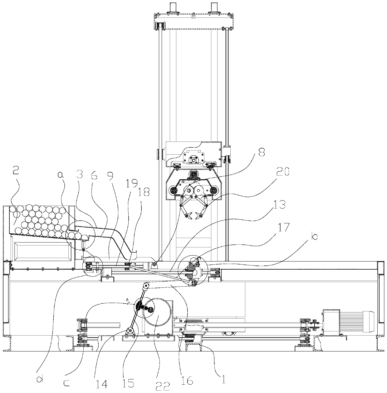
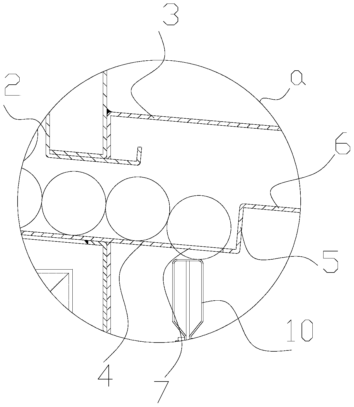
[0031] Such as Figure 1-8 As shown, the present invention includes a frame 1, a feeding trough assembly, a top material flap assembly, a material taking assembly, a transmission assembly and a drive assembly; the feeding chute assembly includes a tank body 2 and a discharge hopper 3, and the tank body 2 is fixedly installed On the frame 1, the tank body 2 is used to place steel pipes. The bottom plate of the tank body 2 is inclined downward from left to right. There is an opening between the lower end of the right side plate of the tank body 2 and the bottom plate of the tank body 2. The width is greater than the diameter of a steel pipe and less than the sum of the diameters of the two steel pipes, so that only one steel pipe can slide out of t...


PUM


Abstract

The invention provides a self-feed feeding device. The self-feed feeding device comprises a rack, a feeding groove assembly, a material ejection turning plate assembly, a material taking assembly, a transmission assembly and a driving assembly; the feeding groove assembly comprises a groove body and a discharging hopper, a material ejection opening is formed in the discharging hopper, and the groove body is used for containing steel pipes; the material ejection turning plate assembly comprises a first hinge seat, a connecting groove and a material ejection block, and the material taking mechanism comprises a material taking groove, a material taking sliding block and a material taking sliding rail; the transmission assembly is used for driving the connecting groove to rotate, the connecting groove is used for driving the material ejection block to upwards penetrate through the material ejection opening to eject the steel pipes and then discharge the steel pipes from the discharging hopper, the steel pipes roll to the material taking groove after being discharged, and the transmission assembly can drive the material taking groove to move to the grabbing position of a manipulator; and the driving assembly is used for driving a rocker to reciprocate left and right. Due to the adoption of the technical scheme, the self-feed feeding device can save time and labor, and can reduce thelabor cost.

Description

technical field [0001] The invention belongs to the technical field of steel pipe manufacturing, in particular to a self-supporting feeding device. Background technique [0002] In the process of steel pipe production and processing, it is necessary to further process the preliminary formed steel pipe blank to make the steel pipe meet the requirements for use. When deep processing the steel pipe, the steel pipe blank needs to be placed in the grasping position of the manipulator, and then the steel pipe is grabbed by the manipulator, and the steel pipe blank is moved to the processing station for deep processing through the rotation and movement of the manipulator. But at present, when loading steel pipe blanks, workers need to continuously put the steel pipes one by one into the grasping position of the manipulator, which not only takes time and effort, but also increases labor costs. Contents of the invention [0003] This invention provides a kind of self-contained fee...

Claims


Application Information

Patent Timeline
Patent Type & Authority Applications(China)
IPC IPC(8): B65G47/82B65G47/90
CPCB65G47/82B65G47/90B65G2201/0217
Inventor 陈绍敏向鹏曾小义唐前辉欧儒春向贤斌姚昌模罗远福鲁冠军梅其政黄丹向上邱明成福群王磊刘建国雷诗轩龚齐斌高倩霞贾明扬裴洋王康宁胡耀文谢欣霖吴鏑胡馨月蒋金陶柳帅向平
Owner CHONGQING ELECTRIC POWER COLLEGE
Why Eureka
Try Eureka