Guide ring device and axial flow fan

A technology of axial flow fan and guide ring, which is applied in axial flow pump, components of pumping device for elastic fluid, mechanical equipment, etc. The effect of improving the air inlet flow field, improving performance and reducing damage

Pending Publication Date: 2020-06-30
浙江科贸实业有限公司
View PDF0 Cites 1 Cited by
  • Summary
  • Abstract
  • Description
  • Claims
  • Application Information

AI Technical Summary

Problems solved by technology

[0003] The purpose of the present invention is to solve the technical problem that the current collecting effect of the guide ring cannot reach the ideal state in the prior art. The invention provides a guide ring device and an axial flow fan

Method used


Image

  • Guide ring device and axial flow fan
  • Guide ring device and axial flow fan
  • Guide ring device and axial flow fan

Examples


Embodiment 1

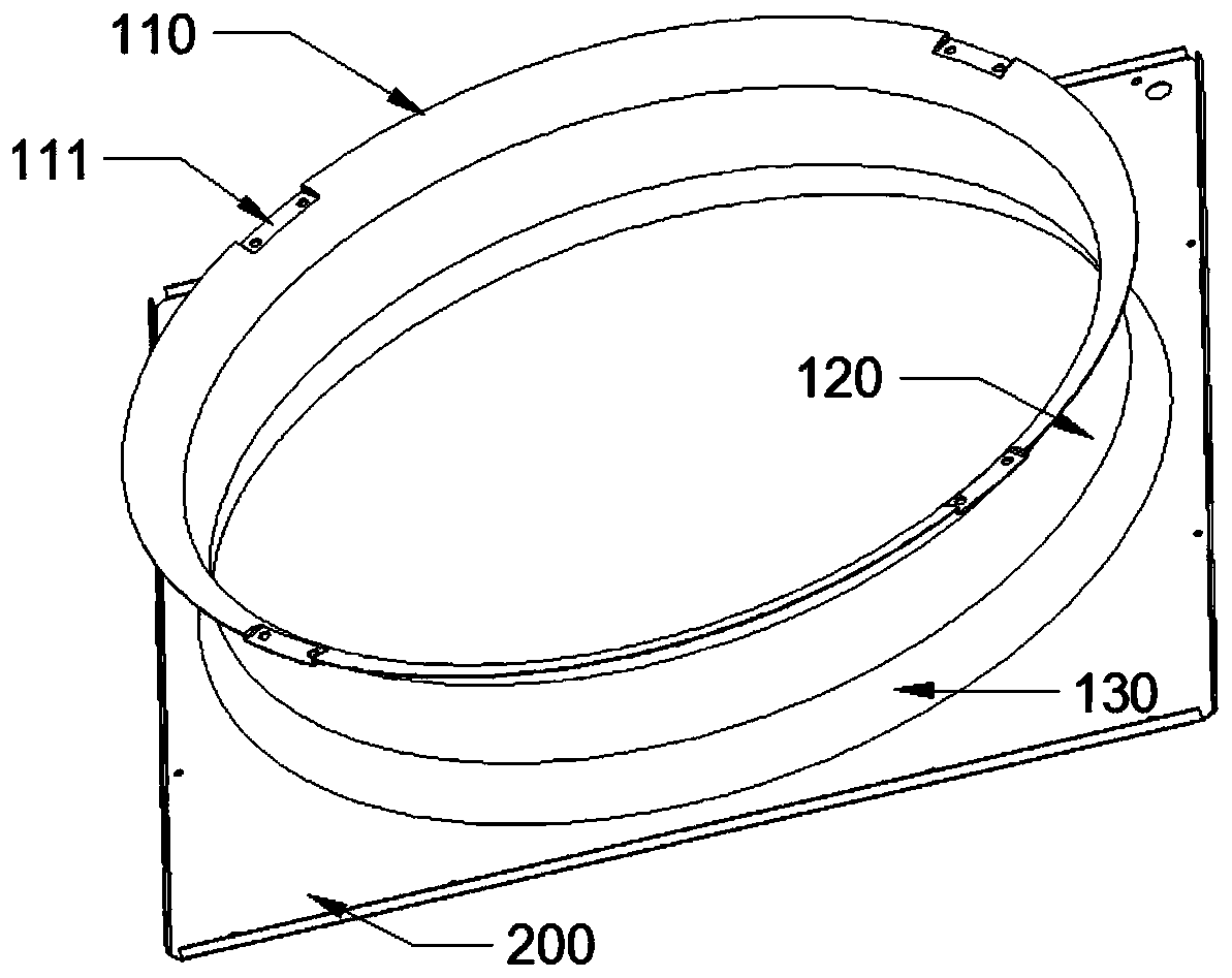
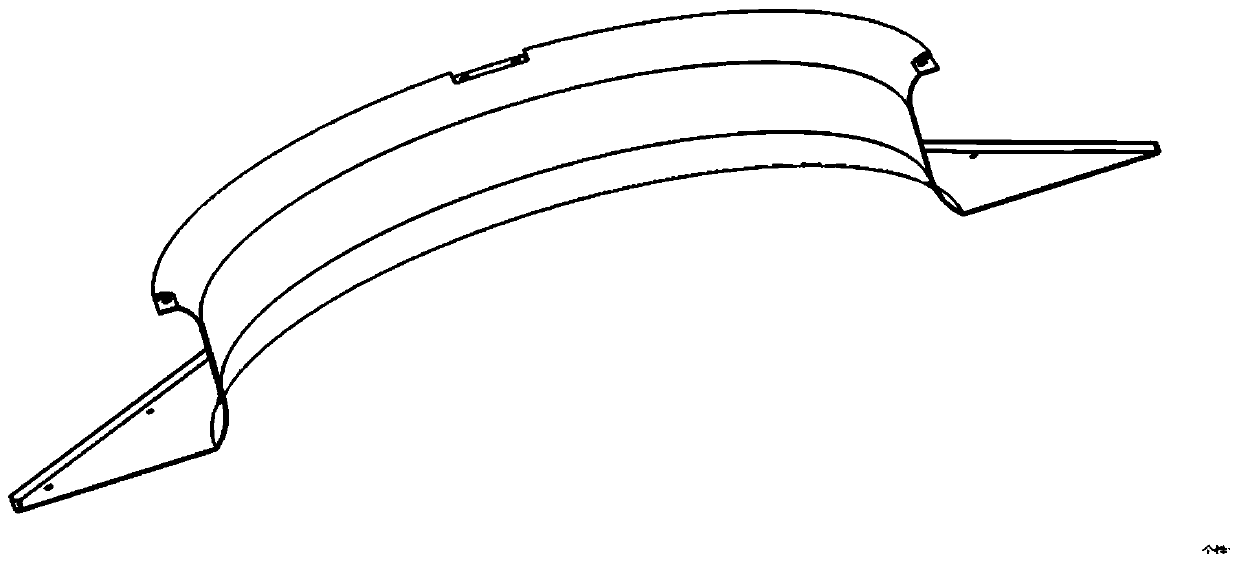
[0022] A guide ring device 100, used for axial flow fans, is arranged on the surface of the axial flow fan installation top plate 200, such as Figure 2-4 As shown, it includes in sequence: an air outlet arc segment 110 , a throat segment 120 and an air inlet arc segment 130 . The upper edge of the circular arc section 110 of the air outlet is outwardly expanded, and the lower edge of the circular arc section 130 of the air inlet is outwardly expanded, and is fixedly connected with the installation top plate 200. The sections 120 are connected, the upper end of the throat section 120 is connected tangentially with the arc section 110 of the air outlet, and the lower end of the throat section 120 is connected tangentially with the arc section 130 of the air inlet.

[0023] The edge of the arc section 110 of the air outlet is provided with an installation platform 111 for installing the grille and the bracket. The setting of the installation platform 111 can reduce the damage to...

Embodiment 2

[0027] An axial flow fan, such as Figure 5 As shown, it includes the wind impeller 300 and the installation top board 200 , and also includes the guide ring device 100 , and the guide ring device 100 is arranged on the installation top board 200 . When the wind impeller 300 is installed, the position K of the section with the largest diameter of the wind impeller is aligned with the upper end point M of the throat section 120 of the guide ring device. When the impeller of axial flow fan is in operation, the blades will inevitably be deformed. The position of the largest diameter section of the impeller is aligned with the upper end point of the throat. The edge rubbing problem of the guide tube in the working condition. The minimum diameter of the guide ring device at the upper end of the throat section 120 is: D+2*δ-2*(a*sinγ), where D is the diameter of the impeller of the axial flow fan, δ is the gap between the impellers, and a is the height of the throat section 120, a...


PUM


Abstract

The invention relates to a guide ring device which is arranged on a mounting top plate of an axial flow fan. The guide ring device comprises an air outlet arc section, a throat section and an air inlet arc section, wherein the upper edge of the air outlet arc section is externally expanded; the lower edge of the air inlet arc section is externally expanded and the air inlet arc section is fixedlyconnected with the mounting top plate; and the throat section is located between the air outlet arc section and the air inlet arc section, the upper end of the throat section is in tangent connectionwith the air outlet arc section, and the lower end of the throat section is in tangent connection with the air inlet arc section. The invention further provides the axial flow fan. The axial flow fancomprises an air impeller, the mounting top plate and the guide ring device, and the position of the maximum section of the air impeller is aligned to the upper end point of the throat section of theguide ring device. The guide ring structure can play an effect similar to a current collector very well, loss coefficient of the structure is reduced, and an intake air flow field is improved.

Description

technical field [0001] The invention relates to the field of fan equipment, in particular to a guide ring device and an axial fan. Background technique [0002] The guide ring is mostly used in the external unit of the air conditioner, and is one of the important components in the air duct of the external unit of the air conditioner that uses the axial flow fan blade. figure 1 As shown, the opening with a radian at the lower end is the air inlet. In the prior art, there is no detailed research on the radian and height of the guide ring. Most of them are based on field experience, and the influence of different radians, heights, and angles on the performance of axial flow fans is lacking. theoretical support. Contents of the invention [0003] The purpose of the present invention is to solve the technical problem that the current collecting effect of the guide ring cannot reach an ideal state in the prior art. The invention provides a guide ring device and an axial flow fa...

Claims


Application Information

Patent Timeline
Patent Type & Authority Applications(China)
IPC IPC(8): F04D29/54F04D19/00F24F1/38
CPCF04D19/002F04D29/541F24F1/38
Inventor 裘霖富张职锋
Owner 浙江科贸实业有限公司
Why Eureka
Try Eureka