
Tolerance characteristic test method, tolerance characteristic test circuit and design method of lightning protection insulator

A technology for lightning protection insulators and characteristic testing, which is applied in the direction of testing dielectric strength, measuring electricity, measuring electrical variables, etc., which can solve the problems that energy and pressure cannot be quickly released, and the ability to withstand impulse current is small.

Active Publication Date: 2020-06-30
HUNAN XIANGDIAN POWER TEST & RES TECH LTD
View PDF6 Cites 4 Cited by
  • Summary
  • Abstract
  • Description
  • Claims
  • Application Information

AI Technical Summary

Problems solved by technology

However, theoretical analysis and on-site operation results show that: during the impulse current test of a single-chip zinc oxide resistor, the resistor is directly exposed to the air environment, and when the entire lightning protection device is formed, multiple resistors in series have been sealed and packaged. The energy and pressure generated by the high-current impact cannot be released quickly, resulting in a smaller surge current withstand capacity of the entire lightning protection device than a single-chip resistor. Therefore, the single-chip zinc oxide resistor and the ratio The surge current withstand characteristics of the unit cannot simulate the actual situation of the entire lightning protection insulator being directly struck by lightning current under the operating conditions

Method used


Image

  • Tolerance characteristic test method, tolerance characteristic test circuit and design method of lightning protection insulator
  • Tolerance characteristic test method, tolerance characteristic test circuit and design method of lightning protection insulator
  • Tolerance characteristic test method, tolerance characteristic test circuit and design method of lightning protection insulator

Examples


Embodiment Construction

[0056] In order to more clearly understand the above objects, features and advantages of the present disclosure, the solutions of the present disclosure will be further described below. It should be noted that, in the case of no conflict, the embodiments of the present disclosure and the features in the embodiments can be combined with each other.

[0057] In the following description, many specific details are set forth in order to fully understand the present disclosure, but the present disclosure can also be implemented in other ways than described here; obviously, the embodiments in the description are only some of the embodiments of the present disclosure, and Not all examples.

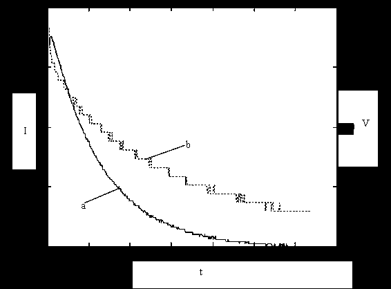
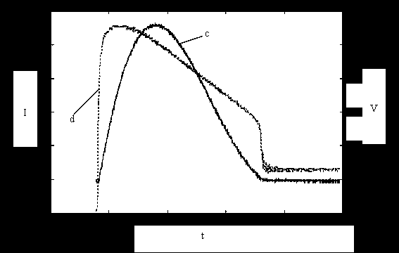
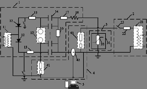
[0058] figure 1 It is a schematic flowchart of a test method for the withstand characteristic of a lightning protection insulator provided by an embodiment of the present disclosure. The test method of the withstand characteristic of the lightning protection insulator can be applied in the scen...


PUM


Abstract

The invention relates to a tolerance characteristic test method, a tolerance characteristic test circuit and a design method of a lightning protection insulator. The test method comprises the following steps: obtaining impact energy absorbed by the whole lightning protection insulator under a first impact current wave; obtaining an impact current and a corresponding thermal stress under a second impact current wave; respectively obtaining a power frequency reference voltage and a leakage current corresponding to the first impact current wave and the second impact current wave; adjusting the impact current applied to the whole lightning protection insulator according to the comparison result of the power frequency reference voltage change rate and the leakage current; and circularly executing the above steps until the obtained power frequency reference voltage change rates are smaller than or equal to a preset change rate and the leakage currents are smaller than or equal to the impactenergy tolerance maximum value and the thermal stress tolerance maximum value corresponding to the whole lightning protection insulator of the preset leakage current. The response characteristics of the whole lightning protection insulator during large-current direct lightning are truly simulated.

Description

technical field [0001] The embodiments of the present disclosure relate to the technical field of electrical equipment testing, and in particular, to a testing method, testing circuit and design method of a lightning protection insulator's withstand characteristic. Background technique [0002] With the development of the economy, the speed of my country's power grid construction has gradually accelerated in recent years. Due to the long transmission distance and wide spanning range, transmission lines often have to pass through some high-altitude mountainous areas with complex terrain, resulting in serious problems of lightning damage in summer and icing in winter. Accidents such as trips, power outages, and equipment damages caused by icing flashovers also occur from time to time. In order to improve the ability of transmission lines to resist lightning strikes and icing disasters, lightning protection insulators can be used to protect against lightning strikes and icing di...

Claims


Application Information

Patent Timeline
IPC IPC(8): G01R31/12
CPCG01R31/1245
Inventor 陆佳政胡建平谢鹏康方针李波
Owner HUNAN XIANGDIAN POWER TEST & RES TECH LTD
Learn More