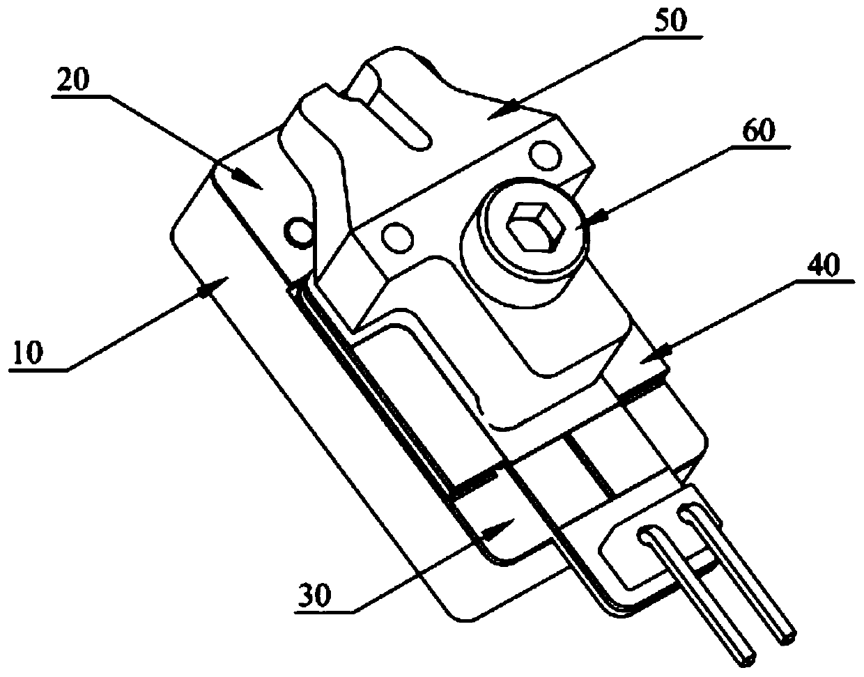
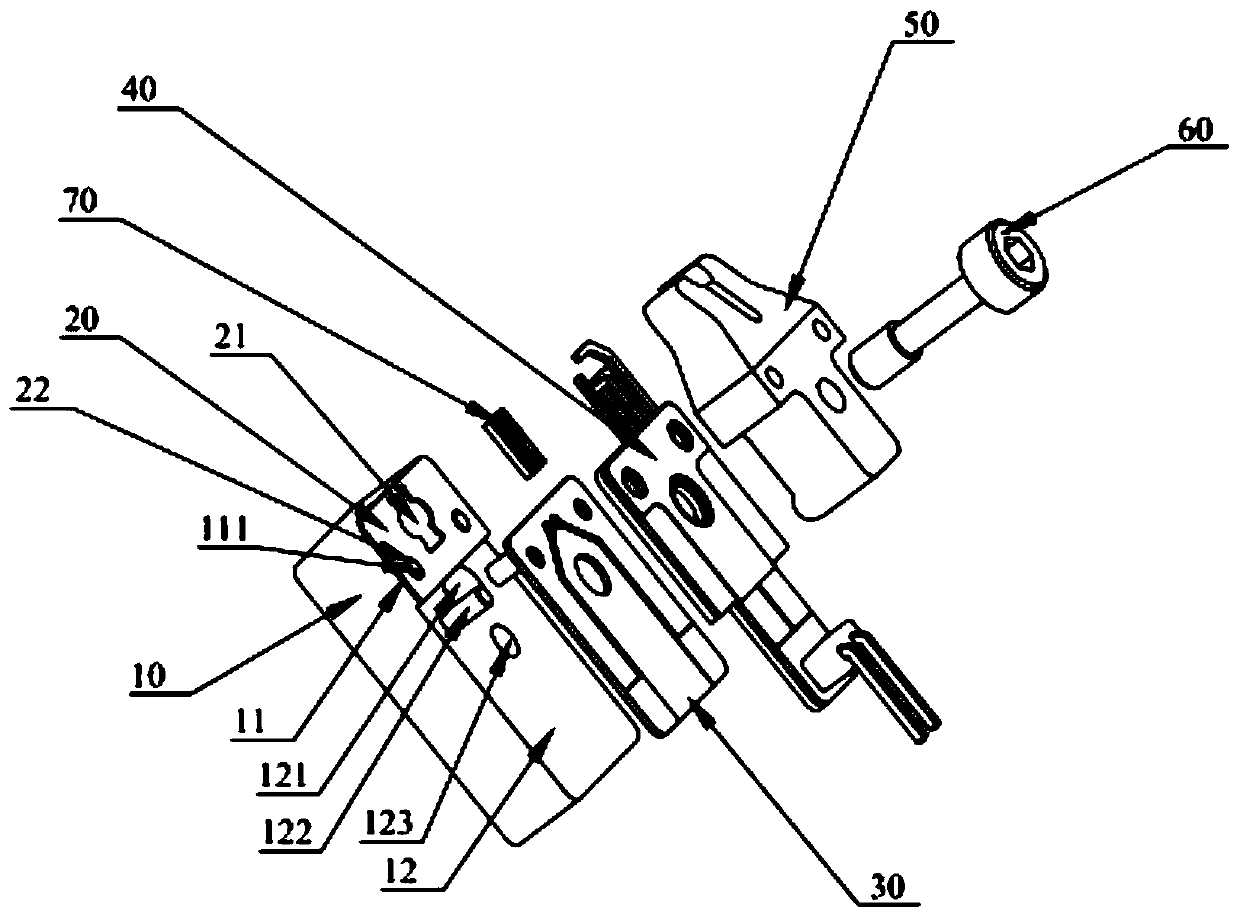
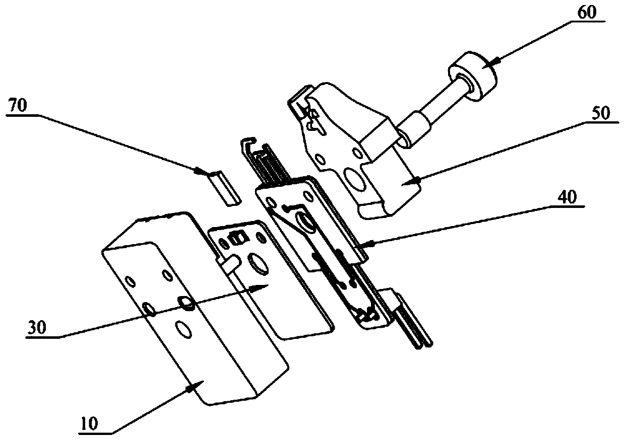
High-power laser chip test aging clamp

A chip testing, high-power technology, applied in the direction of electronic circuit testing, measuring electricity, measuring devices, etc., can solve problems such as inability to achieve independent temperature control, affect test accuracy, poor temperature consistency, etc., to facilitate clamping and production flow , to meet the effect of automated production and improve production efficiency

Pending Publication Date: 2020-06-30
镭神技术(深圳)有限公司
View PDF0 Cites 7 Cited by
  • Summary
  • Abstract
  • Description
  • Claims
  • Application Information

AI Technical Summary

Problems solved by technology

[0002] The aging testing jig of the prior art can generally only test the aging of a single product on one piece of equipment, and the entire jig needs to be replaced to test the aging of another product. The production efficiency is low, and independent temperature control cannot be achieved, resulting in poor temperature consistency. affect test accuracy

Method used


Image

  • High-power laser chip test aging clamp
  • High-power laser chip test aging clamp
  • High-power laser chip test aging clamp

Examples


Embodiment Construction

[0024] In order to make the objectives, technical solutions and advantages of the present invention clearer, the following further describes the present invention in detail with reference to the accompanying drawings and implementation examples. It should be understood that the specific embodiments described here are only used to explain the present invention, but not used to limit the present invention.

[0025] It should be noted that all directional indications (such as up, down, left, right, front, back...) in the embodiment of the present invention are limited to relative positions on the designated view, not absolute positions.

[0026] In addition, in the present invention, descriptions involving "first", "second", etc. are only for descriptive purposes, and cannot be understood as indicating or implying their relative importance or implicitly indicating the number of indicated technical features. Therefore, the features defined with "first" and "second" may explicitly or im...


PUM


Abstract

The invention relates to the technical field of testing and aging equipment, and especially relates to a high-power laser chip test aging clamp. A positioning sheet is fixed on a heat dissipation base, a laser chip is placed on the positioning sheet, a temperature control circuit board is also arranged on the heat dissipation base, a power-up circuit board is arranged above the temperature controlcircuit board, the power-up circuit board is electrically connected with the laser chip, the power-up circuit board is connected with a power supply in test aging equipment, the positioning sheet isprovided with a positioning groove, the laser chip is positioned and placed in the positioning groove, one end of the power-up circuit board is provided with a power-up electrode, the power-up electrode is electrically connected with the laser chip, and the temperature control circuit board is provided with a thermistor. Compared with like clamps in the prior art, the high-power laser chip test aging clamp can test aging of laser chips of different specifications only by adjusting the positioning groove of the positioning sheet and the power-up electrode of the power-up circuit board, so the universality is enhanced, clamping and production circulation of the laser chips are facilitated, and the production efficiency can be improved.

Description

【Technical Field】 [0001] The invention relates to the technical field of testing and burn-in equipment, in particular to a high-power laser chip test burn-in fixture. 【Background technique】 [0002] The test aging fixture of the prior art can generally only perform test aging for a single product on one device, and the entire fixture needs to be replaced to test aging for other products. The production efficiency is low, and independent temperature control cannot be achieved, resulting in poor temperature consistency. Affect test accuracy. [Content of the invention] [0003] In order to overcome the above-mentioned problems, the present invention provides a high-power laser chip test aging fixture that can effectively solve the above-mentioned problems. [0004] A technical solution provided by the present invention to solve the above technical problems is to provide a high-power laser chip test aging fixture, which includes a heat dissipation base on which a positioning sheet is f...

Claims


Application Information

Patent Timeline
Patent Type & Authority Applications(China)
IPC IPC(8): G01R31/28G01R1/04
CPCG01R1/0425G01R31/2856G01R31/2865G01R31/2874
Inventor 李伟罗骏
Owner 镭神技术(深圳)有限公司
Why Eureka
Try Eureka