Foam-molded article, method for producing foam-molded article, and forming mold structure for foam-molded article
A foam molding and manufacturing method technology, applied in the field of foam molding products, can solve the problems of inability to fully eliminate gas residues, dumping and the like
- Summary
- Abstract
- Description
- Claims
- Application Information
AI Technical Summary
Problems solved by technology
Method used
Image

Examples
Deformed example 1
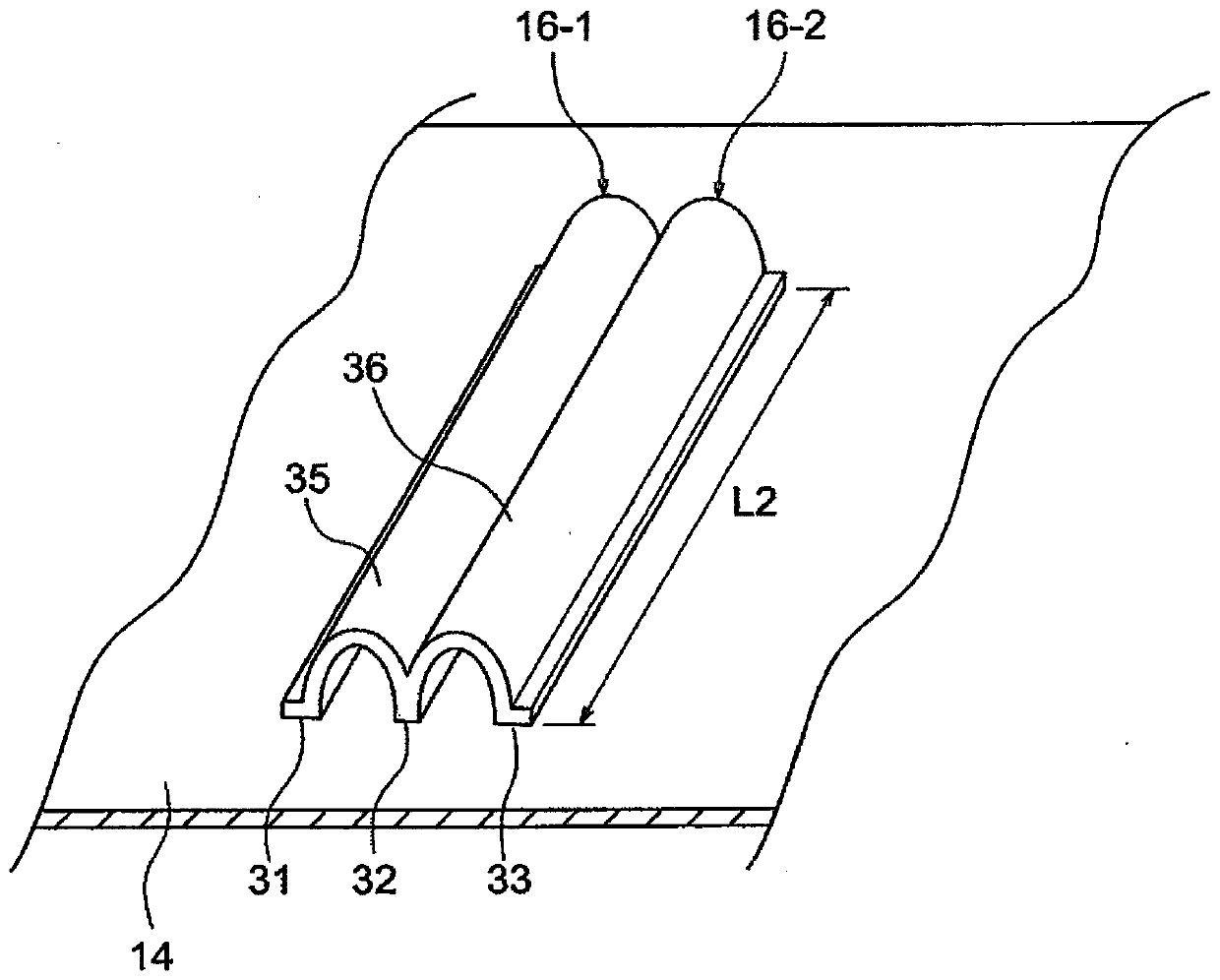
[0101] Figure 8 (a) is a figure for explaining Modification 1 of the protrusion part 16, which shows the state in which the support member 14 was set in the molding die, and Figure 5 The same enlarged view of the main part. The protrusions 16 - 1 and 16 - 2 of Modification 1 are arranged in the width direction of the mold surface shape deformation portion 58 of the convex line (that is, in the width direction of the shape deformation portion 26 of the concave line of the vehicle seat cushion 10 ). ) are separated from each other. Preferably, the entire width dimension W3 of the plurality of protrusions 16 is larger than the width dimension W1 of the die surface shape deforming portion 58 . Furthermore, the protrusion part 16-2 on the downstream side in the flow direction of the foamable resin material is set higher than the protrusion part 16-1 on the upstream side. In addition, the heights of the protrusions 16 - 1 and the protrusions 16 - 2 may be the same height, or ma...
Deformed example 2
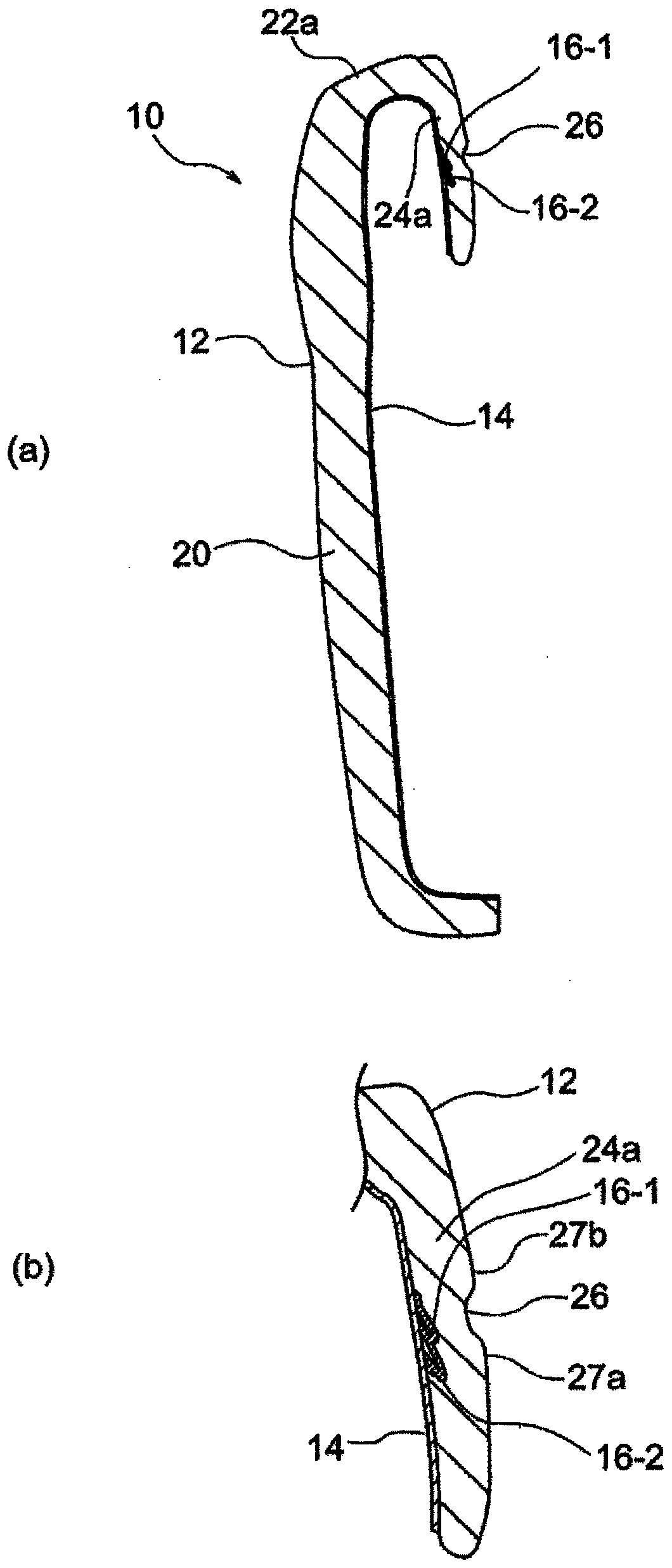
[0104] Figure 8 (b) is a diagram for explaining Modification 2 of the protruding portion 16, which shows a state in which the support member 14 is set in the molding die, and Figure 5 The same enlarged view of the main part. In Modification 2, the plurality of protrusions 16 - 1 , 16 - 2 are all formed in a cylindrical shape with a circular cross section. A plurality of protrusions 16 - 1 , 16 - 2 are formed by one piece of sheet-like member. The protrusion 16 - 1 is formed into a circular cross-section and sewn to the supporting member 14 by a joint portion 71 extending along the extending direction. The protrusion 16 - 2 is formed to have a circular cross-section and is sewn to the support member 14 by one joint portion 72 continuous in the extending direction. In addition, it is possible to make non-joint between the respective joining portions with respect to the support member 14 . By forming and joining each protrusion with one joint in this way, it is possible to f...
Deformed example 3
[0106] Figure 9 It is a figure for explaining the modification 3 of the protrusion part 16, and it shows the state which set the support member 14 in the molding die, and Figure 5 The same enlarged view of the main part. In Modification 3, one protrusion 16 is provided for one shape deformation portion 26 . By providing one protrusion 16 in this way, the structure can be further simplified and the component cost can be reduced.
PUM
 Abstract
Description
Claims
Application Information
 - R&D Engineer
- R&D Manager
- IP Professional
- Industry Leading Data Capabilities
- Powerful AI technology
- Patent DNA Extraction
Browse by: Latest US Patents, China's latest patents, Technical Efficacy Thesaurus, Application Domain, Technology Topic.
© 2024 PatSnap. All rights reserved.Legal|Privacy policy|Modern Slavery Act Transparency Statement|Sitemap