Method and device for detecting the wear state of a component of a door drive system of a rail vehicle

A wear state and drive system technology, applied to vehicle components, registration/indication of vehicle operation, door/window accessories, etc., can solve problems such as inability to ensure rail vehicle operation, insufficient monitoring of wear state, and door system failure

Inactive Publication Date: 2020-06-30
KNORR BREMSE GMBH
View PDF7 Cites 0 Cited by
  • Summary
  • Abstract
  • Description
  • Claims
  • Application Information

AI Technical Summary

Problems solved by technology

[0002] In conventional door drive systems in rail vehicles, the monitoring of the state of wear of the individual components is often not carried out sufficiently, so that in the event of excessive wear of these components, the door system may fail and thus fail to ensure correct operation of the rail vehicle. running

Method used


Image

  • Method and device for detecting the wear state of a component of a door drive system of a rail vehicle
  • Method and device for detecting the wear state of a component of a door drive system of a rail vehicle
  • Method and device for detecting the wear state of a component of a door drive system of a rail vehicle

Examples


Embodiment Construction

[0033] In the subsequent description, identical or similar elements are assigned the same or similar reference symbols in different figures, wherein a repeated explanation of these reference symbols is avoided for reasons of clarity.

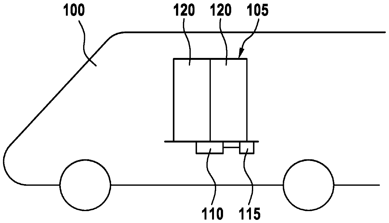
[0034] figure 1 A diagram of a rail vehicle 100 is shown, the doors 105 of which are driven by a door drive system 110 with an electric motor 115 to allow passengers to enter the interior of the rail vehicle 100 . The door drive system 110 can here be designed in such a way that the leaves 120 of the doors 105 are moved away from each other when the door 105 is opened or towards each other when the door 105 is closed. Because such a door drive system 110 is subjected to high and permanent loads during the operation of the rail vehicle 100, individual components of such a door drive system 110 (such as a power transmission belt for force transmission, for lightening the door leaf 120 during the movement stroke) The impact rubber buffer on the en...


PUM


Abstract

The invention relates to a method (700) for detecting the wear state of a component (210, 225, 235) of a door drive system (110) of a rail vehicle (100). The method (700) has a step of reading (710) asequence of first motor parameters (250) and second motor parameters (255), wherein the first motor parameters (250) represent a different physical variable of a motor (115) of the door drive system(110) than the second motor parameters (255). The method (700) additionally has a step (720) of checking whether a value which represents the sequence of the first motor parameters (250) satisfies a specified criterion in order to detect the wear state of the component (210, 225, 235) of the door drive system (115).

Description

technical field [0001] The invention relates to a method and a device for detecting the state of wear of components of a rail vehicle according to the main claims. Background technique [0002] In conventional door drive systems in rail vehicles, the monitoring of the state of wear of the individual components is often not carried out sufficiently, so that in the event of excessive wear of these components, the door system may fail and thus fail to ensure correct operation of the rail vehicle. running. Contents of the invention [0003] Against this background, the object of the present invention is to provide a possibility for improved detection of the state of wear of components of a rail vehicle. [0004] This task is achieved by the solutions of the independent claims. [0005] A method for detecting the state of wear of components of a door drive system of a rail vehicle is currently proposed, wherein the method has the following steps: [0006] - reading in a firs...

Claims


Application Information

Patent Timeline
Patent Type & Authority Applications(China)
IPC IPC(8): E05F15/40E05F15/603E05F15/632E05F15/659
CPCE05Y2900/51E05Y2400/30E05Y2400/458E05Y2800/43E05F15/40E05F15/603E05F15/632E05F15/659B60J5/0497G07C5/0808G07C5/006
Inventor J·布拉毛尔
Owner KNORR BREMSE GMBH
Why Eureka
Try Eureka