
A suspension structure of a power motor for a new energy vehicle

A technology for new energy vehicles and power motors, which is applied in the layout of power units, electric power units, and the combination of cooling and power units, and can solve problems such as insufficient fixing and motor falling off.

Inactive Publication Date: 2021-03-16
LANZHOU JIAOTONG UNIV
View PDF1 Cites 0 Cited by
  • Summary
  • Abstract
  • Description
  • Claims
  • Application Information

AI Technical Summary

Problems solved by technology

[0004] However, this device is only fixed from the side of the power motor, and there is no reinforcement measure on the top, so the fixing is not firm enough, and the motor is easy to fall off from the top

Method used


Image

  • A suspension structure of a power motor for a new energy vehicle
  • A suspension structure of a power motor for a new energy vehicle
  • A suspension structure of a power motor for a new energy vehicle

Examples


Embodiment Construction

[0032] The following will clearly and completely describe the technical solutions in the embodiments of the present invention with reference to the accompanying drawings in the embodiments of the present invention. Obviously, the described embodiments are only some, not all, embodiments of the present invention. Based on the embodiments of the present invention, all other embodiments obtained by persons of ordinary skill in the art without creative efforts fall within the protection scope of the present invention.

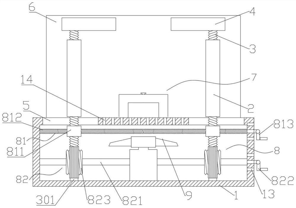
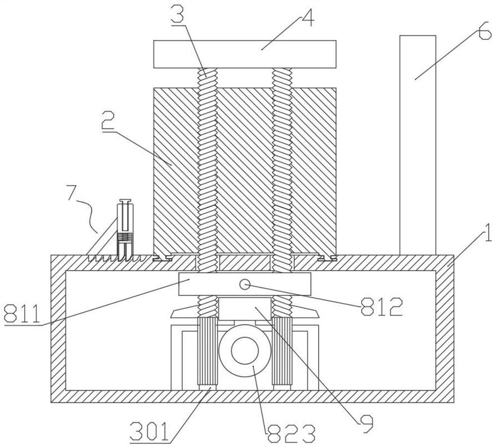
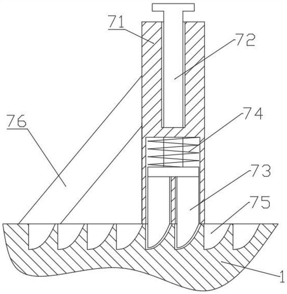
[0033] see Figure 1-6 , the present invention provides a technical solution: a new energy vehicle power motor suspension structure, including a fixed platform 1, the top surface of the fixed platform 1 is provided with two vertical mobile fixed plates 2, the mobile fixed plate 2. Set symmetrically about the left and right sides of the fixed table, and be slidably connected with the top surface of the fixed table 1. Each of the mobile fixed plates 2 is screwed with...


PUM


Abstract

The invention relates to the technical field of automobile product accessories, and concretely relates to a power motor suspension structure for a new energy automobile. The power motor suspension structure comprises a fixed table, movable fixing plates are arranged on the top surface of the fixed table, two first screw rods are in threaded connection with the interior of each movable fixing plate, the top of each first screw rod extends out of the fixed plate and is rotationally connected with a horizontal buckling plate, a vertical fixed baffle is fixed to the rear side of the top of the fixed table, a movable fixed assembly is arranged on the front side of the top of the fixed table, a movable assembly is arranged in an inner cavity of the fixed table, the movable assembly comprises a fixed plate moving mechanism and a buckling plate lifting mechanism, and a cooling fan is arranged in the inner cavity. The fixing plate moving mechanism is arranged, a first crank is rotated to drivea second screw to rotate, the second screw drives the two moving plates to move oppositely, and the two moving plates drive the first screws and the movable fixing plates to move, so that the positions of the two movable fixing plates are adjusted, and the left side and the right side of a driving motor are gradually clamped.

Description

technical field [0001] The invention relates to the technical field of automobile product accessories, in particular to a power motor suspension structure for a new energy automobile. Background technique [0002] For a pure electric logistics van with a mid-mounted rear drive, the power motor is mounted in the middle of the longitudinal beam of the vehicle body to fix the position of the power motor and play a role of support and vibration reduction to ensure the installation of the power motor and the NVH of the vehicle ( Noise, Vibration, Harshness, key components of noise, vibration and harshness) performance. [0003] For example, the patent number CN201721586185.4 discloses a suspension structure of a power motor for a new energy vehicle, including a cylinder, a connecting rod, a pressure plate, a spring, a baffle, a damping spring, a base, a suction cup, a support platform, an air outlet, and a baffle Three, the upper end of the support platform is fixed with a cylin...

Claims


Application Information

Patent Timeline
Patent Type & Authority Patents(China)
IPC IPC(8): B60K1/00B60K11/06
CPCB60K1/00B60K11/06B60K2001/006
Inventor 武祥冯志超宋克伟常立民王良璧张永恒
Owner LANZHOU JIAOTONG UNIV
Learn More