
Water pipe winding equipment for garden watering

A sprinkler and water pipe technology, applied in the field of gardens, can solve the problems of heavy water pipes and surface wear of water pipes, and achieve the effect of preventing wear

Inactive Publication Date: 2020-07-03
郭振
View PDF0 Cites 2 Cited by
  • Summary
  • Abstract
  • Description
  • Claims
  • Application Information

AI Technical Summary

Problems solved by technology

[0003] When the existing winding device winds the water pipe, since the water has just been sprinkled, there will be water stains inside the water pipe. When the water pipe is wound, the water inside the water pipe may cause water damage. Heavy weight, which may cause abrasion to the surface of the hose when reeling

Method used


Image

  • Water pipe winding equipment for garden watering
  • Water pipe winding equipment for garden watering
  • Water pipe winding equipment for garden watering

Examples


Embodiment 1

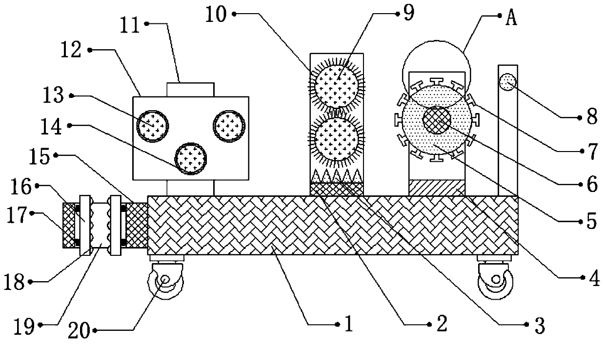
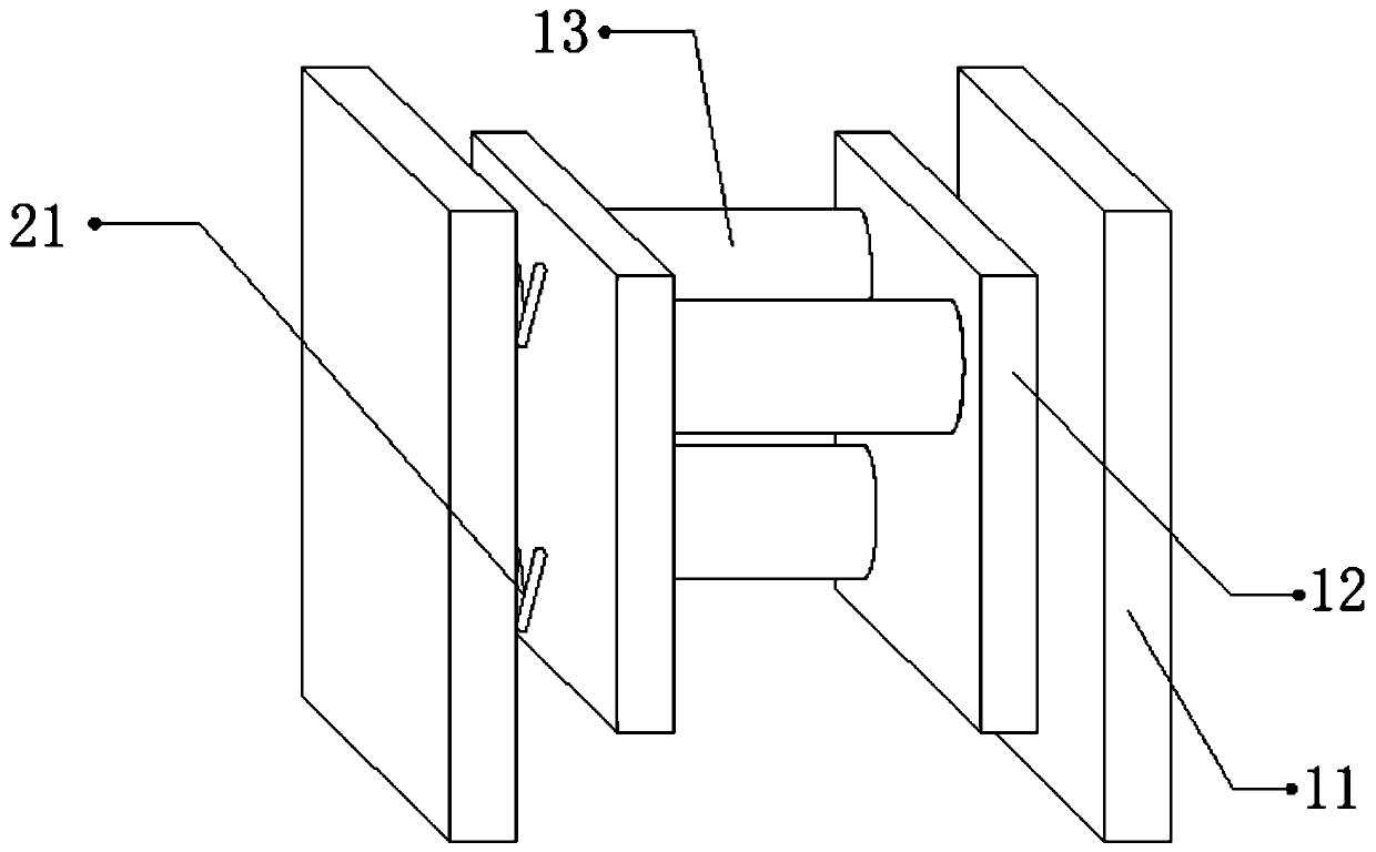
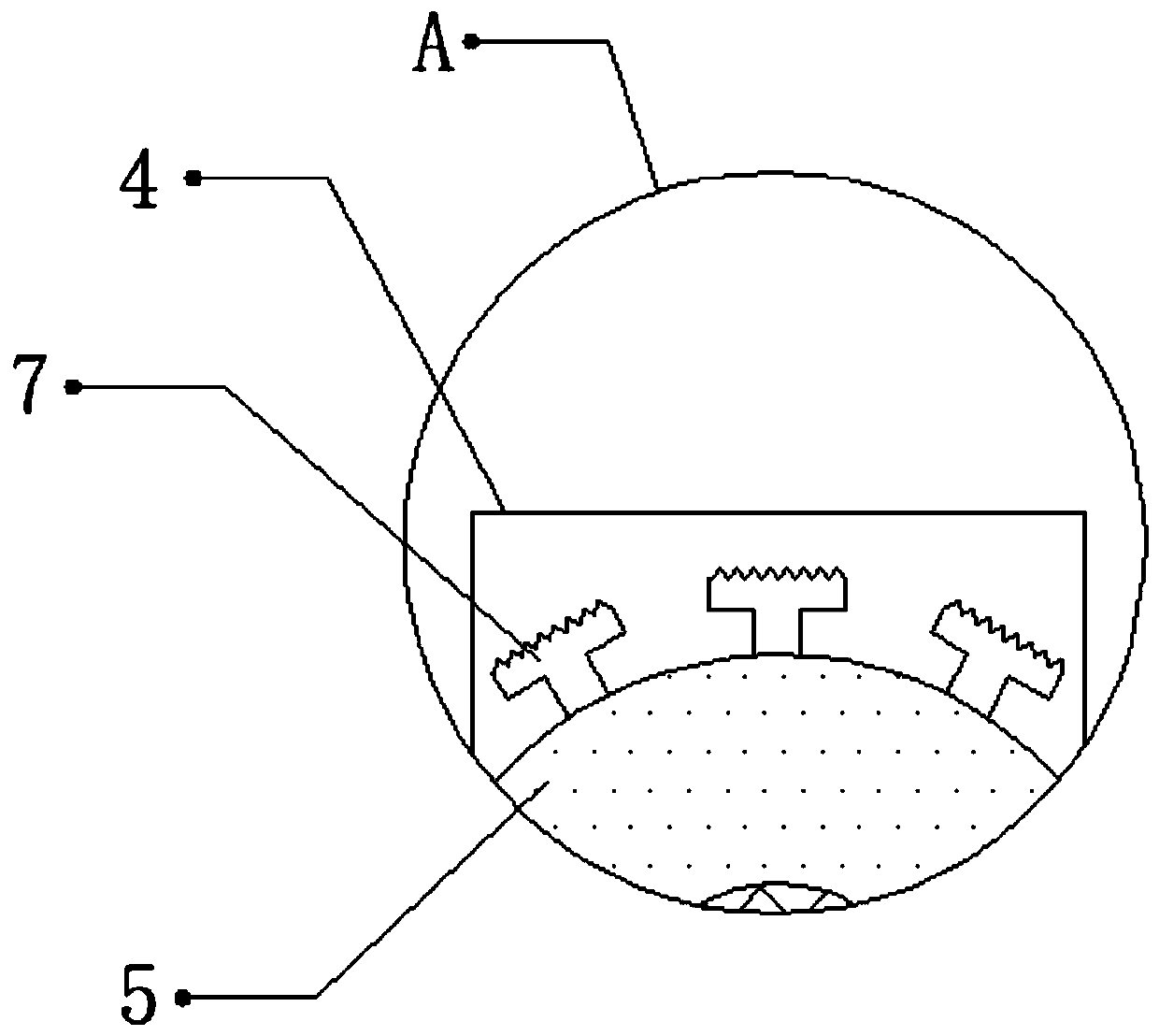
[0030] refer to Figure 1-3 , a garden sprinkling water pipe winding equipment, including a fixed seat 1, one side of the outer wall of the fixed seat 1 is connected with a connecting plate 15 by bolts, and the top outer wall of the connecting plate 15 is provided with a fixed port 19, and the two opposite sides of the fixed port 19 The side inner walls are connected with two springs 17 by bolts, and the outer wall of one side of the springs 17 is connected with a splint 16 by bolts, and the outer wall of the opposite side of the two splints 16 is provided with a ball groove, and the inner wall of the ball groove is rollingly connected with a ball 18. One side of the outer wall of the top of the fixed seat 1 is connected with a support frame 4 by bolts, and the outer wall of the opposite side of the support frame 4 is connected with a rotating shaft 6 in rotation, and the outer wall of the rotating shaft 6 is connected with a winding roller 5 by bolts, and the winding The oute...

Embodiment 2

[0041] refer to Figure 4 , a garden sprinkling water pipe rewinding device. Compared with Embodiment 1, the four corners of the bottom outer wall of the fixed seat 1 are connected with the second moving wheel 22 by bolts, and the shape of the second moving wheel 22 is petal-shaped. , so that the equipment will vibrate when it moves, so that the larger debris adhering to the surface of the water pipe can be processed through the vibration.

[0042]Working principle: When in use, when the water pipe needs to be rewound, one end of the water pipe is rewound on the rewinding roller 5, and the device is moved by the push rod 8 and the second moving wheel 22, and the second moving wheel 22 The shape is petal-shaped, so that the equipment will vibrate when it moves, so that the larger debris adhering to the surface of the water pipe can be processed through the vibration. During this period, start the motor, and the motor will drive the winding roller 5 to rotate, thereby The water...


PUM


Abstract

The invention discloses water pipe winding equipment for garden watering. The water pipe winding equipment comprises a fixing seat, wherein a connecting plate is fixedly connected to the outer wall ofone side of the fixing seat, a fixing opening is formed in the outer wall of the top of the connecting plate, two springs are fixedly connected to the inner wall of each of the two opposite sides ofthe fixing opening, clamping plates are fixedly connected to the outer walls of one sides of the springs, ball grooves are formed in the outer walls of the opposite sides of the two clamping plates, balls are connected to the inner walls of the ball grooves in a rolling mode, a supporting frame is fixedly connected to one side of the outer wall of the top of the fixing seat, a rotating shaft is rotationally connected to the outer walls of the opposite sides of the supporting frame, and a winding roller is fixedly connected to the outer wall of the rotating shaft. The equipment can prevent water stains from remaining in a water pipe to cause heavy weight of the water pipe, can prevent the surface of the water pipe from being abraded due to friction, can prevent the water pipe from being scattered on equipment due to inertia generated during winding, and can treat large-size debris attached to the surface of the water pipe.

Description

technical field [0001] The invention relates to the technical field of gardens, in particular to a garden sprinkling hose winding device. Background technique [0002] The beautiful natural environment and recreational areas created by using engineering technology and artistic means in a certain area by transforming the terrain, planting trees and flowers, building buildings and arranging garden roads are called gardens. Workers often sprinkle the garden, and some areas are not easy for sprinklers to pass through. Therefore, an external water pipe is required to sprinkle the garden through the water pipe. Therefore, after the water pipe is used, it is usually necessary to wind the water pipe through the winding equipment. [0003] When the existing winding device winds the water pipe, since the water has just been sprinkled, there will be water stains inside the water pipe. When the water pipe is wound, the water inside the water pipe may cause water damage. The heavy weigh...

Claims


Application Information

Patent Timeline
Patent Type & Authority Applications(China)
IPC IPC(8): B65H54/22B65H54/46B65H54/72B65H59/10B65H75/18B08B1/02B08B1/00F26B21/00B08B1/20
CPCB65H54/22B65H54/46B65H54/72B65H59/10B65H75/18F26B21/00B65H2515/31B65H2701/33B08B1/20B08B1/12
Inventor 郭振
Owner 郭振
Learn More