
Shield machine shield shell back soil removing device

A shield machine, back soil technology, applied in earth-moving drilling, mining equipment, tunnels, etc., can solve the problems of poor ductility and low soil fragmentation efficiency, and achieve the effect of reducing soil adsorption.

Inactive Publication Date: 2020-07-03
YIWU INDAL & COMMERICAL COLLEGE
View PDF1 Cites 0 Cited by
  • Summary
  • Abstract
  • Description
  • Claims
  • Application Information

AI Technical Summary

Problems solved by technology

[0004] However, the folding and stretching of the board surface used above can take advantage of the poor ductility of the soil to tear the large piece of soil into multiple small pieces, thereby preventing the pile of soil on the back of the shield machine. This kind of folding and stretching is too inefficient to indirectly fragment the soil

Method used


Image

  • Shield machine shield shell back soil removing device
  • Shield machine shield shell back soil removing device
  • Shield machine shield shell back soil removing device

Examples


Embodiment Construction

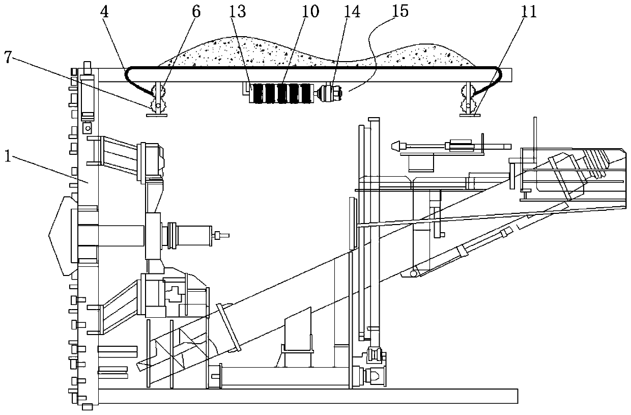
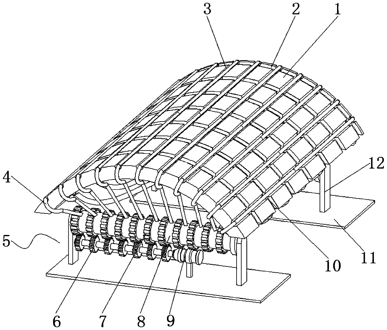
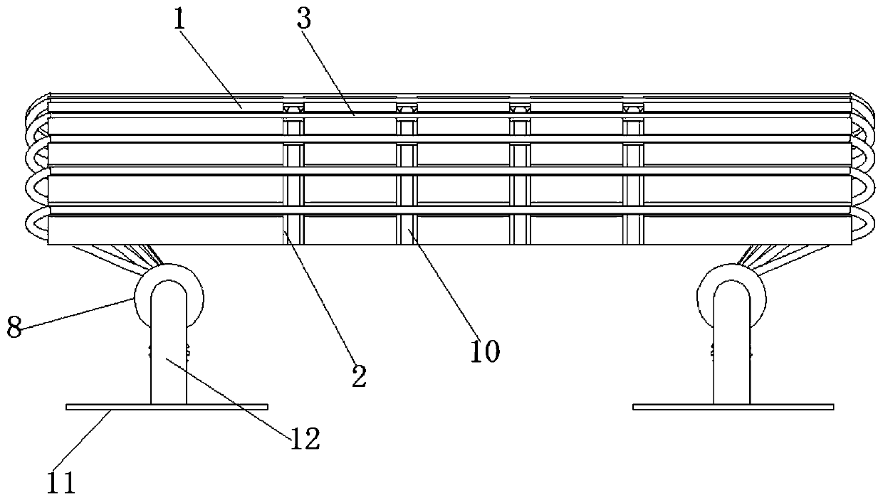
[0021] The embodiment of the present invention provides a device for removing the back soil of the shield shell of the shield machine, such as Figure 1-4 As shown, it is set on the shell of the shield machine 1. It includes two driving mechanisms-5, a plurality of steel cables-4 and longitudinal grooves 3. A plurality of longitudinal grooves 3 are equidistantly arranged on the casing of the shield machine 1 . The two driving mechanisms one 5 are both arranged in the shield machine 1 . The steel cable-4 is slidably fitted in the longitudinal groove 3, and the two ends of the steel cable-4 are linked with the two driving mechanisms-5 respectively. The driving mechanism one 5 includes a base plate 11 , a bracket 12 , a plurality of take-up wheels 1 8 , a plurality of linkage gears 7 , a driving gear 6 and a motor 1 9 . The bottom plate 11 is arranged on the inner wall of the shield machine 1 . The bracket 12 is arranged on the bottom plate 11 . The take-up wheel one 8 and t...


PUM


Abstract

The invention provides a shield machine shield shell back soil removing device. The shield machine shield shell back soil removing device is arranged on a shell of a shield machine. Two drive mechanisms I, a plurality of steel cables I, and longitudinal grooves are provided. The plurality of longitudinal grooves are equally spaced on the shell of the shield machine. The two drive mechanisms I aredisposed within the shield machine. The steel cables I are slidably matched in the longitudinal groove. Two ends of the steel cable I are correspondingly in linkage connection with the two driving mechanisms. According to the shield machine shield shell back soil removing device, the drive mechanisms I, the plurality of steel cables I and the longitudinal grooves are matched with each other, so that soil adsorbed on the shield machine can be effectively removed. The cutting effect of a cutter can be approximately embodied by using the repeated saw pulling movement of the cables. Large soil blocks can be cut into small blocks. Meanwhile, functions of a transport tool can be embodied to force cut soil to move, so that soil adsorption force is reduced, and the probability that the soil slidesaway from the shield machine 1 is increased.

Description

technical field [0001] The invention relates to the technical field of shield tunneling machine equipment, in particular to a device for removing back soil from a shield shell of a shield tunneling machine. Background technique [0002] When the shield machine is constructed in the mudstone formation, due to the viscosity of the soil and the huge pressure, the soil sticks tightly to the outside of the shield shell of the shield machine to form a back soil phenomenon. When the shield machine advances, if the back soil cannot break away from the shield shell and advance together with the shield machine, it will cause serious disturbance of the surrounding soil layer, causing the surface to bulge or collapse; at the same time, due to the soil sticking to the shield shell, the shield machine will The resistance increases, and in severe cases, the propulsion cylinder cannot overcome the resistance received, causing the shield machine to be stuck. Therefore people specially inven...

Claims


Application Information

Patent Timeline
Patent Type & Authority Applications(China)
IPC IPC(8): E21D9/06E21D9/12
CPCE21D9/06E21D9/12
Inventor 吴俊峰吴华君熊晨超徐淼升冯利坡
Owner YIWU INDAL & COMMERICAL COLLEGE
Learn More