Movable joint assembly

A technology of assembly and joint, applied in the directions of shafts and bearings, mechanical equipment, pivots, etc., can solve the problems of complex device structure and unstable angle locking, and achieve the effect of simple and reliable structure

Pending Publication Date: 2020-07-03
重庆中泽拓邦生物技术有限公司
View PDF2 Cites 10 Cited by
  • Summary
  • Abstract
  • Description
  • Claims
  • Application Information

AI Technical Summary

Problems solved by technology

However, the above-mentioned device has problems such as complex structure and unstable angle locking. For the situation where long-term

Method used


Image

  • Movable joint assembly
  • Movable joint assembly
  • Movable joint assembly

Examples


Embodiment 1

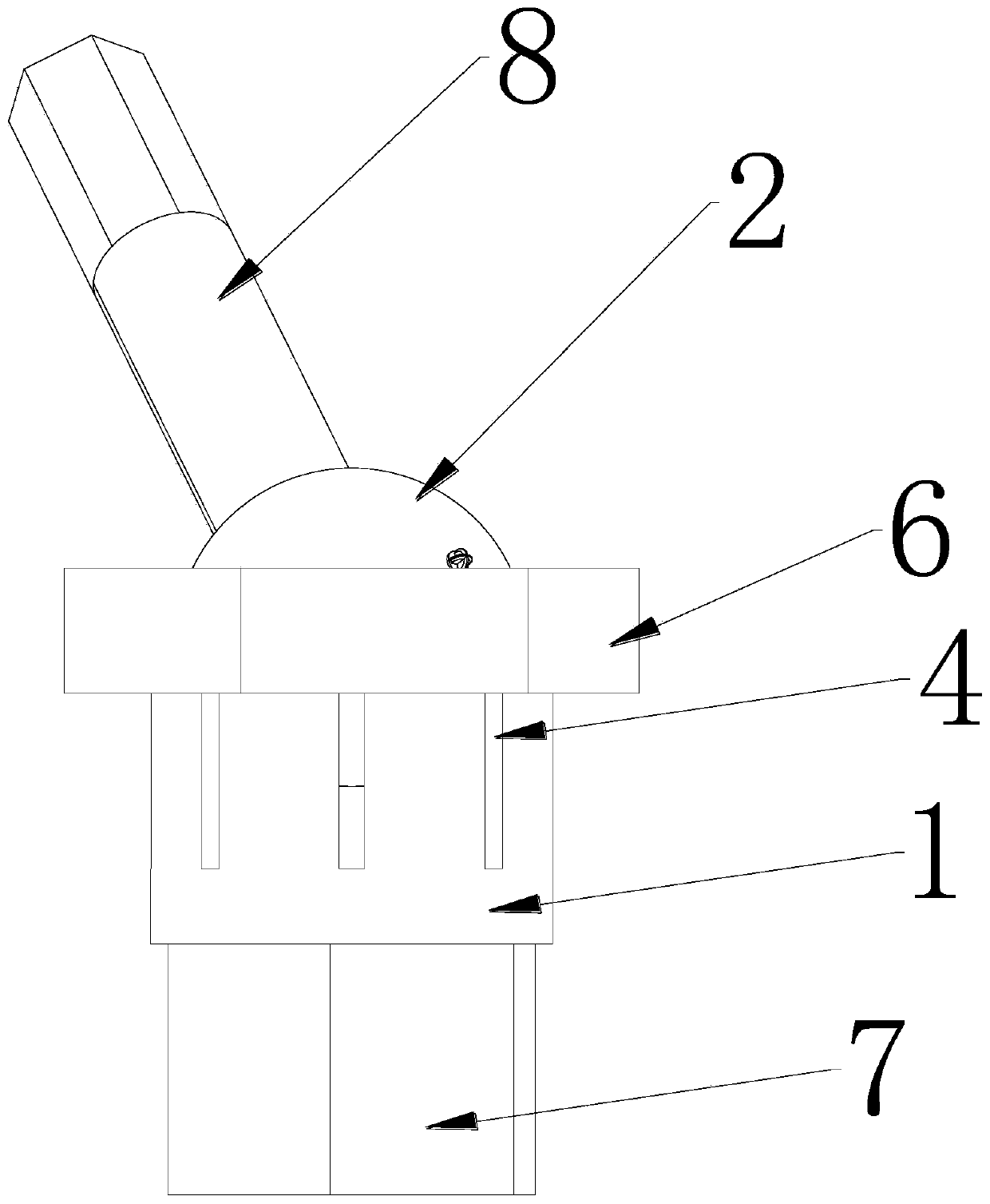
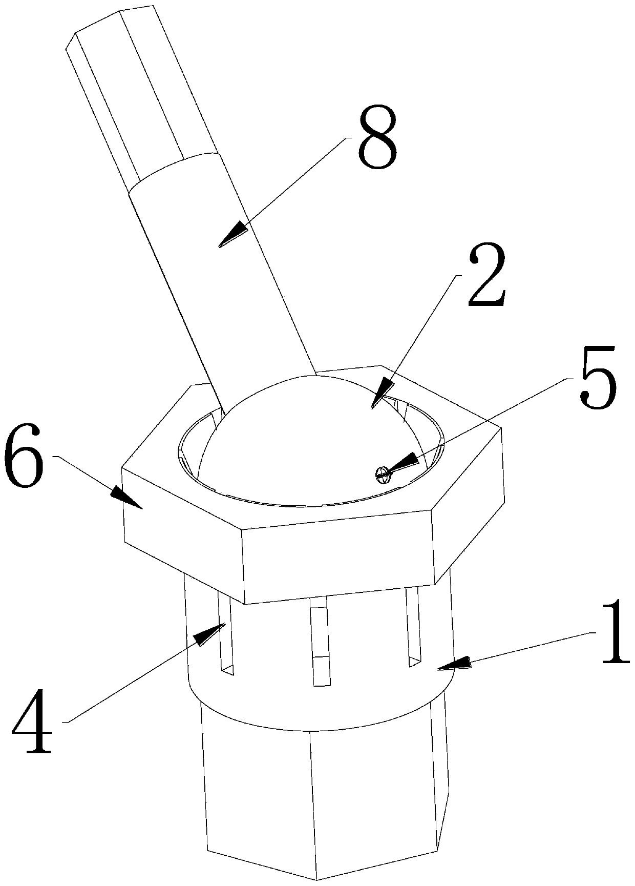
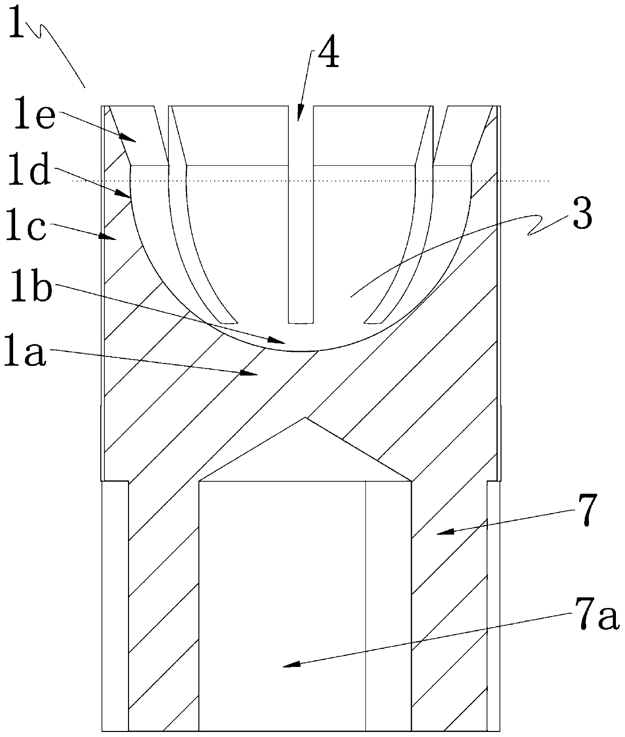
[0048] Such as Figure 1~4 As shown, a joint assembly includes a ball seat 1 and a ball head 2, the ball seat 1 includes a ball seat body, the ball seat body is provided with a ball head chamber 3, and the ball head chamber 3 is provided with a The adapted ball head 2. The ball seat body is provided with a bar-shaped notch 4, and the bar-shaped notch 4 extends out of the opening of the ball head chamber 3, and the ball seat body corresponding to the ball head chamber 3 is provided with an encircling locking mechanism 6 When the embracing locking mechanism 6 hugs the ball seat body corresponding to the ball head cavity 3 from the outside, the strip-shaped notch 4 allows the ball seat body parts on both sides to deform inward to press and lock the ball seat body. Describe the ball head 2.

[0049] The purpose of setting the bar-shaped notch 4 is: the existence of the bar-shaped notch 4 reduces the strength of the ball seat body at its location, and forms a space for making roo...

Embodiment 2

[0065] The difference from Embodiment 1 is that, as Figure 8 and 9 , the pressing protrusion 5 is fixedly arranged on the inner surface of the toothed portion 1c, and the outer surface of the ball head 2 is deformed when pressed by the pressing protrusion 5 . In this embodiment, the pressing protrusion 5 is provided on the inner surface of the tooth-shaped portion 1c, and the pressing protrusion 5 is conical. The hardness of at least the part near the outer surface of the ball head 2 is less than that of the pressing protrusion 5, and when the tooth-shaped portion 1c is pressed against the ball head 2, the pressing protrusion 5 is pressed into or pierces the outer surface of the ball head 2, such as Figure 10 and 11 shown.

[0066] This design makes the holding effect of the ball seat 1 to the ball head 2 better and more stable in the locked state. Further, pressure-sensitive adhesive may also be filled between the inner surface of the ball head cavity 3 and the outer s...


PUM


Abstract

The invention discloses a movable joint assembly which comprises a ball seat and a ball head. The ball seat comprises a ball seat body. A ball head cavity is arranged on the ball seat body. The ball head matched with the ball head cavity is arranged in the ball head cavity. A strip-shaped gap is formed on the ball seat body and extends out of an opening of the ball head cavity. A surrounding locking mechanism is arranged at the position, corresponding to the outer side of the ball seat body, of the ball head cavity. When the surrounding locking mechanism tightly holds the position, corresponding to the ball head cavity, of the balls seat body from the outer side, the strip-shaped gap allows the parts, on the two sides of the strip-shaped gap, of the ball seat body to deform inwards so as to jack and lock the ball head. The movable joint assembly has the beneficial effects that the ball seat body has certain deformation cavity, the ball head can be placed conveniently and can be freelyadjusted to the proper angle, then the ball head is locked by the surrounding locking mechanism, and the structure is simple and reliable.

Description

technical field [0001] The invention belongs to the technical field of movable connectors, and in particular relates to a movable joint assembly. Background technique [0002] The universal joint is a universal joint, which is a mechanism that realizes variable angle connection in space. It is similar to a "joint". The common ones are cross universal joints, ball joints, etc., and are widely used in industry, transportation, medical treatment, etc. each field. In general, the universal joint changes with the movement of the components connected to it, and realizes the function of freely changing the angle. However, in some cases, it is also necessary to have a locking function to fix the angle so that the position of the components connected to it is fixed. When the cross universal joint is used, two cross universal joints whose motion planes are perpendicular to each other are connected in series, or the two ends of the cross universal joint are respectively connected to ...

Claims


Application Information

Patent Timeline
IPC IPC(8): F16C11/06F16C11/10
CPCF16C11/0623F16C11/106
Inventor 周文兴
Owner 重庆中泽拓邦生物技术有限公司
Why Eureka
Try Eureka