Local scanning method based on airborne photoelectric system

A technology of photoelectric system and scanning method, which is applied in the directions of navigation, instrumentation, surveying and navigation, etc.

Active Publication Date: 2020-07-03
西安应用光学研究所
View PDF13 Cites 3 Cited by
  • Summary
  • Abstract
  • Description
  • Claims
  • Application Information

AI Technical Summary

Problems solved by technology

[0006] The technical problem to be solved by the present invention is: how to overcome the disadvantageous influ

Method used


Image

  • Local scanning method based on airborne photoelectric system
  • Local scanning method based on airborne photoelectric system
  • Local scanning method based on airborne photoelectric system

Examples


Embodiment 1

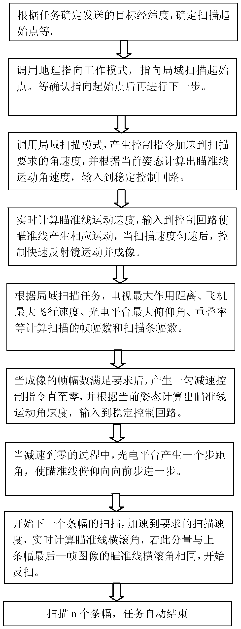
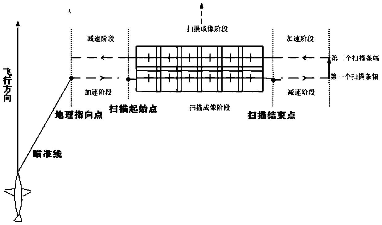
[0165] This embodiment is directed to a line-of-sight local scanning control method based on a certain photoelectric system, which is implemented by a local scanning software package in an airborne photoelectric system. During the horizontal flight of the carrier aircraft, it maintains an approximately uniform straight line flight. The local scanning area is generally located on the side of the carrier aircraft’s flight path, and the line of sight pitch angle is relatively large, such as figure 2 Shown. When the local scanning software package receives a local scanning instruction, the local scanning software package will figure 1 The shown process completes the following solution process.

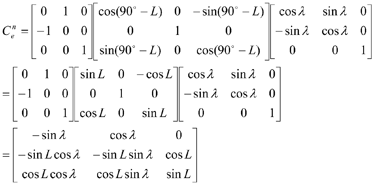
[0166] The first step is to set the altitude h=5km, speed v=220km / h, heading ψ=60°, roll angle γ=0.35°, pitch angle θ=0.5° at the starting point on the left side of the uniform scan. Longitude λ=108.76923°, latitude L=34.61158°. Roll angle of photoelectric platform , Pitch angle β=-5°.

...


PUM


Abstract

The invention belongs to the technical field of airborne photoelectric reconnaissance monitoring, and particularly relates to a local scanning method based on an airborne photoelectric system. By converting the attitude of the carrier aircraft and the angle of the photoelectric platform and combining the speed, height and scanning starting point of the carrier aircraft during level flight, the movement speed of the photoelectric platform is calculated in real time according to the frame frequency, field angle, overlapping rate and the like of the sensor, and the influence of carrier aircraft movement, especially course disturbance, can be overcome. The aiming line control instruction is corrected, the trajectory of the aiming line on the ground is corrected into a straight line perpendicular to the trajectory, the problem that the motion trajectory of the aiming line on the ground is a parabola instead of a non-straight line during local scanning under the condition that the pitch angle of a photoelectric platform is large is solved, image splicing is easy, and an operator can monitor a target in an electronic map easily.

Description

Technical field [0001] The invention belongs to the technical field of airborne photoelectric reconnaissance and monitoring, and specifically relates to a local scanning method based on an airborne photoelectric system. The method can control the photoelectric system in real time to review in wide-area scanning splicing images, and perform local seamless on the ground. Geographic scanning to achieve target tracking, motion state estimation and positioning. Background technique [0002] The current information warfare places higher requirements on target reconnaissance and surveillance. Continuous, comprehensive, accurate and efficient theater surveillance and target reconnaissance is one of the important conditions for winning an information war. A reconnaissance and surveillance system is a photoelectric mission equipment with a manned / unmanned aircraft as the carrying platform. It has the characteristics of wide coverage area, long range, precise geographic positioning of targe...

Claims


Application Information

Patent Timeline
IPC IPC(8): G01C21/16
CPCG01C21/165
Inventor 刘栋王惠林杜佩雷亮王冠陈鸣张璟玥姜世洲梁冰吴辉贺剑
Owner 西安应用光学研究所
Why Eureka
Try Eureka