
A near-field measurement method and system for planar antennas with reduced truncation error

A planar antenna, truncation error technology, applied in the direction of the antenna radiation pattern, etc., can solve the problems of low efficiency, low near-field test efficiency, large scanning area, etc.

Active Publication Date: 2020-08-14
SHANGHAI HOLLYWELL ELECTRONICS SYST TECH
View PDF2 Cites 0 Cited by
  • Summary
  • Abstract
  • Description
  • Claims
  • Application Information

AI Technical Summary

Problems solved by technology

However, for larger array antennas (array antenna), this will result in too large a scanning area, making near-field testing inefficient
For example, to test a reflector antenna with a working frequency of 30GHz and an aperture of 1.5m, when the scanning surface is a rectangle of 2.4m×2.4m, the sampling interval is 5mm, and the sampling rate is 80mm / s, it takes 7 hours. very low
If the scanning area is reduced, the limited scanning area truncation error will definitely have a greater impact on the measurement results

Method used


Image

  • A near-field measurement method and system for planar antennas with reduced truncation error
  • A near-field measurement method and system for planar antennas with reduced truncation error
  • A near-field measurement method and system for planar antennas with reduced truncation error

Examples


Embodiment Construction

[0053] A function whose Fourier transform is zero for frequency values ​​outside the finite interval centered on the origin is called a band-limited function. When the function f(t) satisfies the band-limited condition, that is, when w>w c When , the frequency spectrum f(w)=0 of f(t), where w represents frequency, w c Indicates the boundary frequency of the function f(t). The extrapolation for band-limited function algorithm can recover f(t) from finite samples of f(t) in a given interval.

[0054] For planar near-field antenna measurements, the aperture field (aperturefield) is considered zero outside the aperture of the antenna under test, thus satisfying the band-limit condition. Therefore, the process of determining the plane wave spectrum from the finite field measured by the plane near-field antenna can be equivalent to a mathematical model of band-limited function extrapolation.

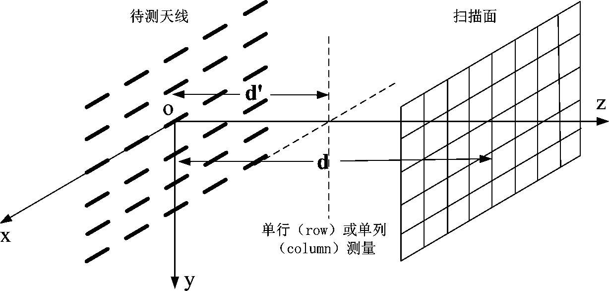
[0055] see figure 1 , which is a simplified model of a planar antenna. The antenna to...


PUM


Abstract

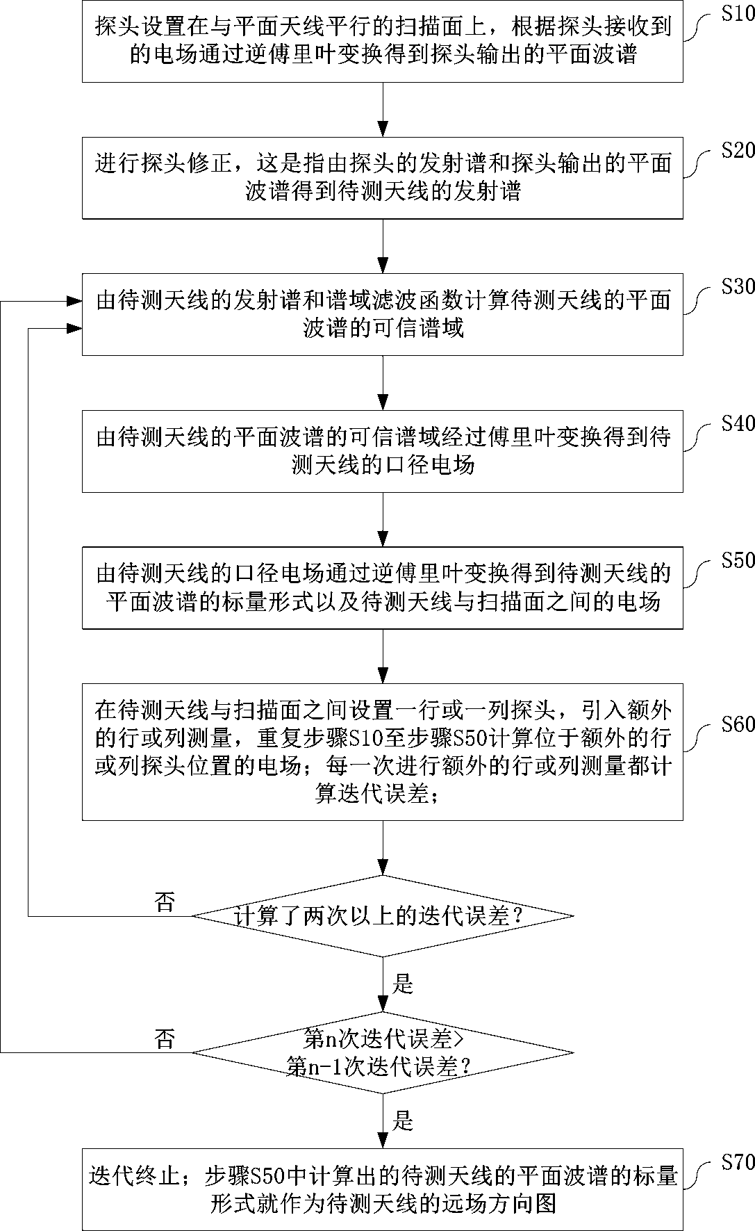
The invention discloses a planar antenna near-field measurement method capable of reducing truncation errors, which comprises the steps of obtaining a plane wave spectrum output by a probe through inverse Fourier transform according to an electric field received by the probe; carrying out probe correction; calculating the credible spectral domain of the plane wave spectrum of a to-be-measured antenna according to the emission spectrum of the to-be-measured antenna and a spectral domain filtering function; obtaining an aperture electric field of the to-be-measured antenna through Fourier transform according to the credible spectral domain of the plane wave spectrum of the to-be-measured antenna; performing inverse Fourier transform according to the aperture electric field of the to-be-measured antenna to obtain a scalar form of the plane wave spectrum of the to-be-measured antenna and an electric field located between the to-be-measured antenna and the scanning surface; introducing additional row or column measurement, and calculating an electric field located at the position of an additional row or column probe; calculating an iterative error for each additional row or column measurement; and repeating until the nth iteration error is greater than the (n-1)th iteration error, and terminating iteration. According to the invention, the truncation error problem in planer near-field measurement is reduced based on a band-limited function extrapolation algorithm.

Description

technical field [0001] The present application relates to an antenna measurement technology, in particular to a planar antenna measurement method based on planar near field scanning and capable of reducing truncation errors. Background technique [0002] According to the basic theory of planar near-field measurement, in order to accurately determine the far-field pattern of the antenna under test (far-field pattern, also known as radiation pattern or antenna pattern), in principle, it is required to record the antenna under test The output of the probe (probe) on the previous infinite plane requires that the scanning plane (scanning plane) should be infinite. However, in actual measurement, the scanning plane is always limited, and the field outside the finite scanning plane is assumed to be zero, so the determination of the antenna far-field pattern by the near-field-far-field transformation will inevitably bring errors. This kind of error caused by the limited scanning su...

Claims


Application Information

Patent Timeline
Patent Type & Authority Patents(China)
IPC IPC(8): G01R29/10
CPCG01R29/10
Inventor 周建华栗曦毛小莲杨林
Owner SHANGHAI HOLLYWELL ELECTRONICS SYST TECH
Learn More