Rigidity adjusting device for spiral springs and tuned mass damping device

A technology of adjusting device and coil spring, applied in the direction of non-rotational vibration suppression, etc., can solve the problems of weakening the control effect of TMD vibration reduction, reducing the applicability of TMD device, and difficult to adjust the stiffness of spring unit, so as to achieve convenient and effective adjustment of stiffness and quality, Practical value of large projects, simple structure effect

Active Publication Date: 2014-07-16
CHINA AVIATION PLANNING & DESIGN INST GRP
View PDF4 Cites 12 Cited by
  • Summary
  • Abstract
  • Description
  • Claims
  • Application Information

AI Technical Summary

Problems solved by technology

[0004] TMD is sensitive to the tuning frequency, and frequency misalignment will significantly reduce the effectiveness of TMD, and even bring adverse effects on the controlled structure. Once the spring unit of the existing TMD vibration damping device is installed, it is difficult to adjust the stiffness, which is prone to frequency misalignment.
In addition, roll and swing are prone to occur during the vertical vibration of the mass block. Although the existing TMD adopts guide rods and other devices to avoid roll and swing to a certain extent, the device produces different degrees of noise pollution during operation, which reduces the TMD. At the same time, once the fastening bolts of the damping mass block are loosened, local vibration of the mass will be caused, which will also weaken the vibration damping control effect of TMD

Method used


Image

  • Rigidity adjusting device for spiral springs and tuned mass damping device
  • Rigidity adjusting device for spiral springs and tuned mass damping device
  • Rigidity adjusting device for spiral springs and tuned mass damping device

Examples


Embodiment 1

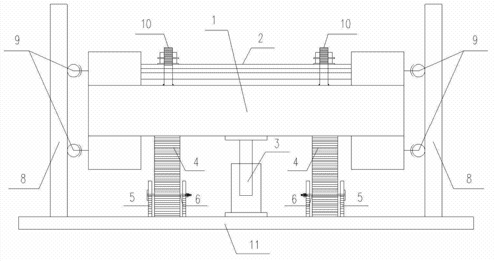
[0035] Such as figure 1 As shown, the adjustable vertical tuning mass damping device proposed by the present invention mainly includes a fixed mass 1, an adjustable mass 2, a viscous damper 3 and a coil spring 4, wherein the adjustable mass 2 is welded to the fixed mass The fixed screw rod 10 on the block 1 is bolted to the fixed mass block 1, and the coil spring 4 extends into the fixed end cylinder 5 and is fixed to the connecting part 11 (it can be a beam-type, plate-type or truss-type connecting part), and the other end of the coil spring 4 It is fixed at the bottom of the mass block, and the fixed end cylinder 5 is provided with a clamping hole 7 (the structure of the fixed end cylinder and the clamping plate shows the views Figure 5 , Figure 6 ), the clamp plate 6 passes through the spring 4 through the clamp hole 7 on the fixed end cylinder 5, and the guide wheel 9 is welded to the mass block 1 and pre-pressed to guide the side plate 8. When the vibration occurs, th...

Embodiment 2

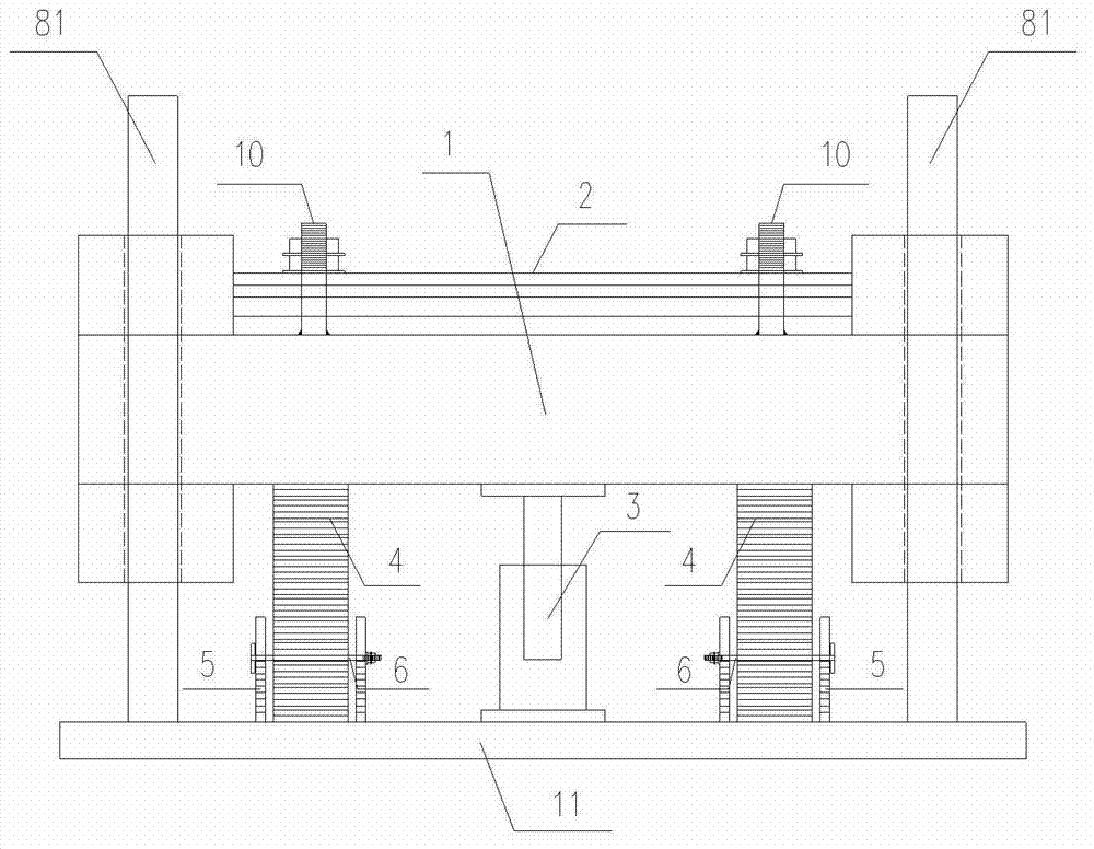
[0041] Such as figure 2 As shown, the difference from the first embodiment is that the guide device in the second embodiment adopts a guide rod. What is different from the traditional guide rod is that the present invention proposes to add isolation on the surface of the guide rod 81 and in the preset guide hole of the mass block. Materials, specifically, elastic materials with low coefficient of friction or lubricating materials can be used, such as: liquid lubricating oil, soap-based and non-soap-based grease, graphite, polytetrafluoroethylene, etc.; sleeves can also be placed on the guide rod and guide Between the holes, the section of the sleeve 18 is as Figure 7 As shown, the sleeve is provided with a chute, and the guide rod contacts the guide hole through the ball 19 in the sleeve chute. In actual work, the guide rod vibrates up and down along the guide hole, which changes the sliding friction between the traditional guide rod and the guide hole. for rolling friction...

Embodiment 3

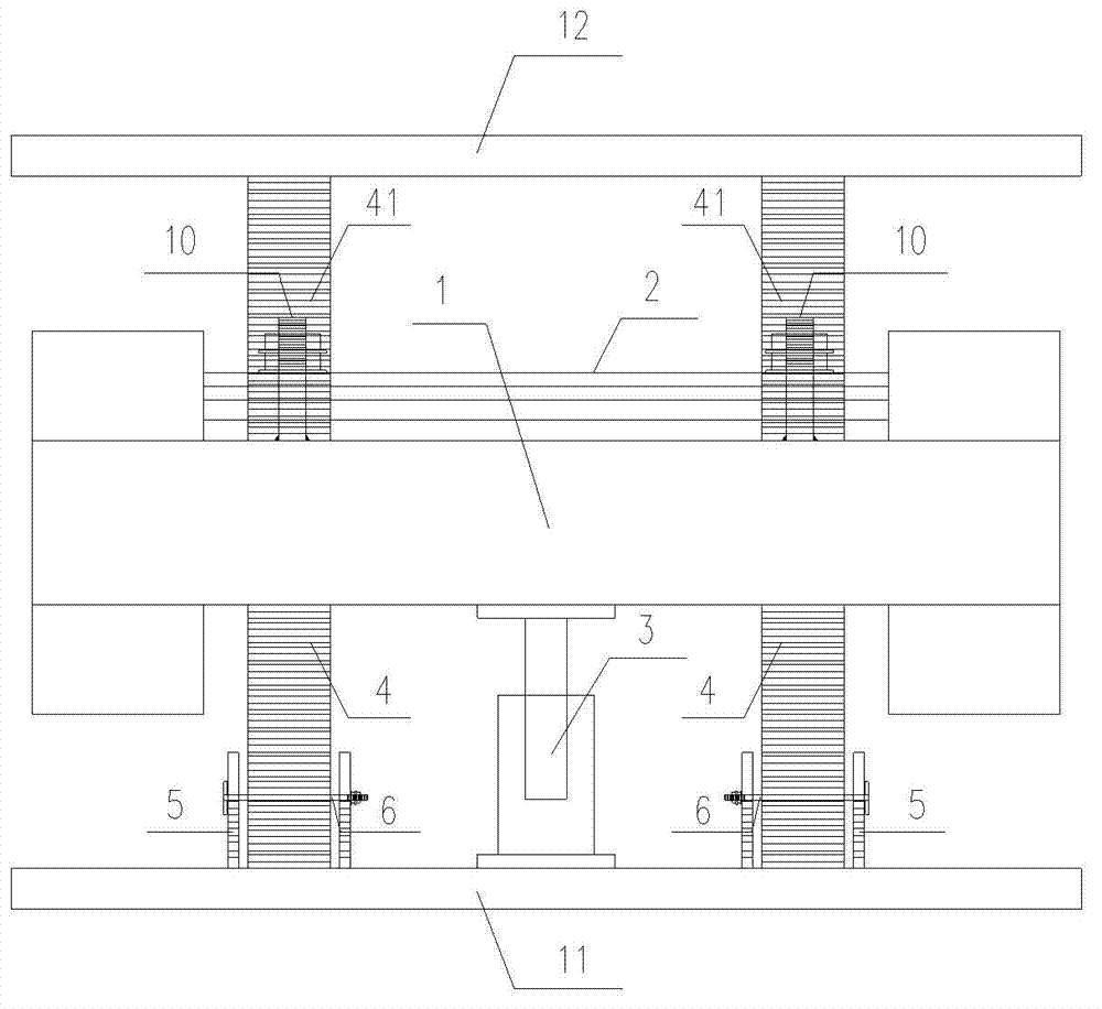
[0043] Such as image 3 As shown, different from the specific embodiment 1, the adjustable vertical tuning mass damping device proposed by the present invention adopts 8 sets of double-layer symmetrical springs, and the mass block 1 and the mass block 2 are placed between the spring 4 and the spring 41. , the setting of double-layer springs can effectively avoid the shaking and overturning of the mass block during the vibration process, and can realize self-guiding without additional guiding devices, which ensures the vibration reduction control effect of the device and simplifies the structure at the same time. When the device is connected to the main structure, a support pier needs to be set vertically at the structural layout position according to the building space and the size of the device, and the vertical stiffness of the support pier must meet the requirement that the deformation of the adjustable vertical tuning mass damping device is not greater than 2mm during opera...


PUM


Abstract

Disclosed is a rigidity adjusting device for spiral springs. The spiral springs are compressed and stretch along the first direction. The rigidity adjusting device comprises a bearing seat and clamping plates, wherein the bearing seat is at least provided with two support portions oppositely arranged along the second direction, the support portions extent along the first direction, the second direction is perpendicular to the first direction, one ends of the spiral springs are disposed between the two support portions, each support portion is provided with at least one bayonet, and the bayonets on one support portion is arranged oppositely to the corresponding bayonet of the other support portion along the second direction; one ends of the clamping plates are supported on the bayonet of one of the support portions, the other ends of the same are supported on the bayonet of the other support portion, and the clamping plates applicably penetrate the spiral springs between the two support portions.

Description

technical field [0001] The invention relates to the field of structure damping control, in particular to a stiffness adjustment device for a coil spring and a tuning mass damping device. Background technique [0002] The tuned mass damper (TMD) adopts the vibration reduction strategy of tuned vibration absorption. It is a vibration reduction strategy that relies on imposing an inertial mass on a certain part of the structure, and is equipped with a spring unit and a damping unit. The vibration mode is controlled by the inertial mass and the main structure. A vibration damping device that absorbs and consumes the vibration energy of the main structure through resonance. [0003] Because TMD has little impact on building functions, occupies only a small part of the building space, and is easy to install, repair and replace, it is widely used in pedestrian bridges, vertical vibration control of long-span structures, and wind-induced response control of high-rise structures. en...

Claims


Application Information

Patent Timeline
Patent Type & Authority Applications(China)
IPC IPC(8): F16F15/04
Inventor 付仰强王明珠葛家琪张玲管志忠马伯涛
Owner CHINA AVIATION PLANNING & DESIGN INST GRP
Why Eureka
Try Eureka