Device for cleaning ink reservoir, printing machine, and method for cleaning ink reservoir

A technology for cleaning devices and printing machines, which is applied to the general parts of printing machinery, printing machines, printing, etc., and can solve the problem that the ink transfer roller is not divided into separate rollers, etc.

Inactive Publication Date: 2020-07-03
I MAR PLANNING INC
View PDF2 Cites 0 Cited by
  • Summary
  • Abstract
  • Description
  • Claims
  • Application Information

AI Technical Summary

Problems solved by technology

In addition, with regard to the conventional ink transfer roller, the entire roller moves forward and backward relative to the ink fountain roller, and the ink transfer roller is not divided into individual rollers.

Method used


Image

  • Device for cleaning ink reservoir, printing machine, and method for cleaning ink reservoir
  • Device for cleaning ink reservoir, printing machine, and method for cleaning ink reservoir
  • Device for cleaning ink reservoir, printing machine, and method for cleaning ink reservoir

Examples


Embodiment

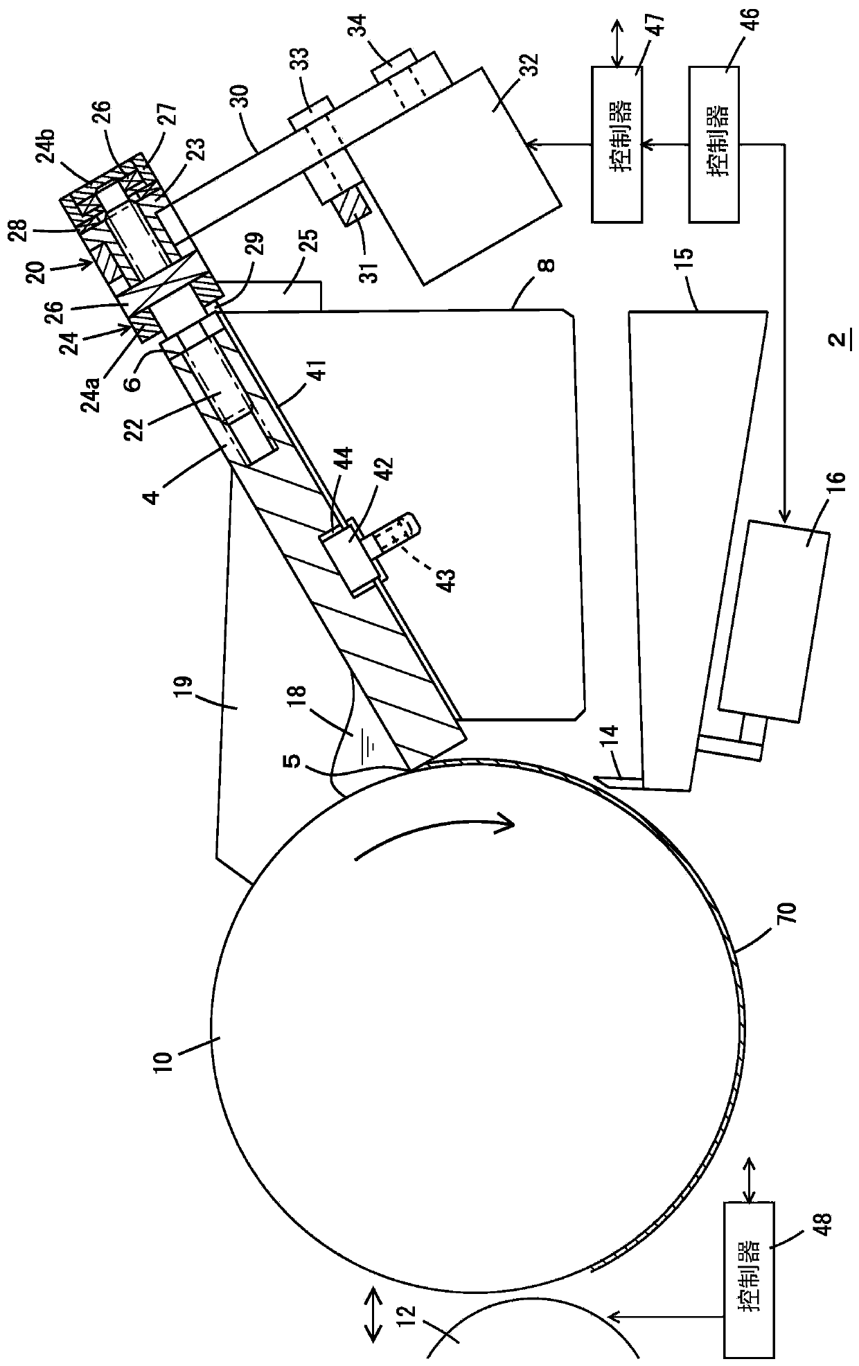
[0072] Figure 1-Figure 10 Indicates an example. figure 1 Indicates the main part of a printing machine, and the type of printing machine may be, for example, an offset printing machine or a letterpress printing machine. The printing target may be paper, or an optical disc such as a can, CD-ROM, or the like. In the case of a tank, an optical disk, etc., impurities such as water mixed in from the water tray are removed from the ink container.

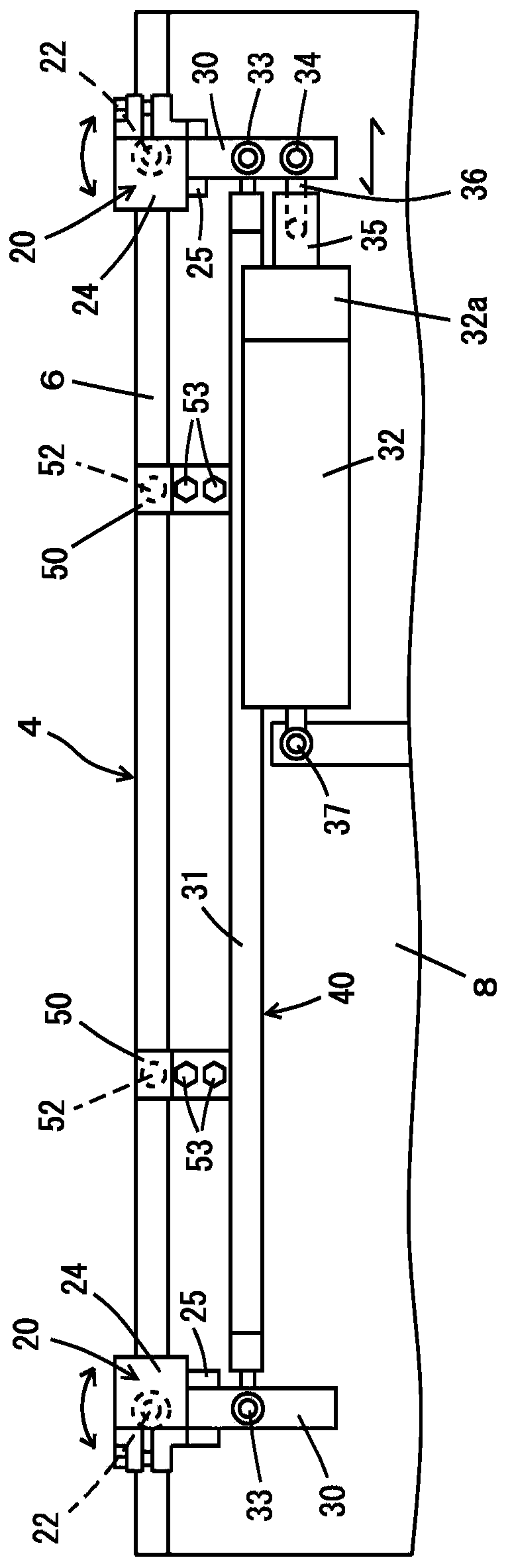
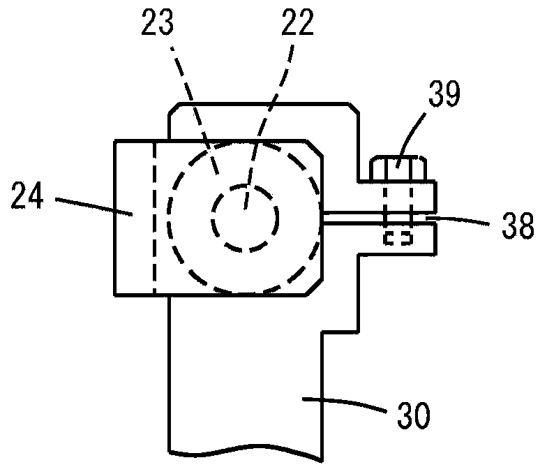
[0073] The front end 5 of the ink fountain 4 is opposite to the ink fountain roller 10, so that the gap between the front end 5 and the roller 10 can be changed into the following three types: close contact (for example, less than 10 μm) with a gap of approximately zero, normal (for example, about 0.05mm-0.2mm), Cleaning (eg about 0.2-0.3mm). A pair of left and right feed screw mechanisms 20 are provided at the base end 6 of the ink fountain 4 , and the ink fountain 4 is slid to the above-mentioned three positions by moving the stud s...


PUM


Abstract

In a printing machine, an ink reservoir is formed between an ink fountain and an ink fountain roller, and then ink is supplied to a plate cylinder via a ductor roller that is capable of moving forwardand backward with respect to the ink fountain roller. The printing machine is provided with: a base which supports the ink fountain; the ink fountain; a slide mechanism which controls a gap between the tip of the ink fountain and the ink fountain roller by sliding the ink fountain along the base; a cleaner which removes ink from the ink fountain roller; a forward / backward motion mechanism which moves the cleaner back and forth between a position at which the cleaner comes into contact with the ink fountain roller and a non-contact position; and a controller. The controller performs control onthe slide mechanism and the forward / backward motion mechanism, expands the gap so as to allow both ink and impurities therein to pass through the gap, and brings the cleaner into contact with the inkfountain roller to remove the ink and impurities therein from the roller.

Description

technical field [0001] The present invention relates to the cleaning of ink containers in printing presses. Background technique [0002] With the increase in the frequency of printing on recycled paper, there has been a problem of contamination of printing machines due to paper dust. The paper dust is attached to the ink from the squeegee, etc., and moves to the ink fountain side, and is clogged in the gap between the ink fountain and the ink fountain roller. At the same time, the amount of ink supplied to the ink transfer roller via the ink fountain roller is reduced, and the printing density is reduced. Therefore, the operator needs to clean the ink fountain to remove the paper dust, but this becomes a burden on the operator, and printing needs to be stopped during cleaning. [0003] The related prior art is shown below. In Patent Document 1 (Japanese Patent No. 3194174), the surface of the ink fountain is covered with a freely wound and fed sheet, and the ink can be r...

Claims


Application Information

Patent Timeline
Patent Type & Authority Applications(China)
IPC IPC(8): B41F31/05B41F31/14B41F35/04
CPCB41F31/05B41F31/14B41F35/04B41P2235/20B41F31/04B41F31/08B41F31/20B41P2235/21
Inventor 井爪雅幸
Owner I MAR PLANNING INC
Why Eureka
Try Eureka