Home sick-bed with convenient replacement of bed sheets

A bed sheet and family technology, applied in the field of family hospital beds, can solve the problems of patient injury, laborious and time-consuming nursing work, trouble, etc.

Pending Publication Date: 2020-07-07
SHAOYANG UNIV
View PDF0 Cites 2 Cited by
  • Summary
  • Abstract
  • Description
  • Claims
  • Application Information

AI Technical Summary

Problems solved by technology

When existing family beds are used for nursing care of paralyzed patients and serious patients who have lost their ability to take care of themselves, the nursing work is laborious and time-consuming. If the patien

Method used


Image

  • Home sick-bed with convenient replacement of bed sheets
  • Home sick-bed with convenient replacement of bed sheets
  • Home sick-bed with convenient replacement of bed sheets

Examples


Embodiment 1

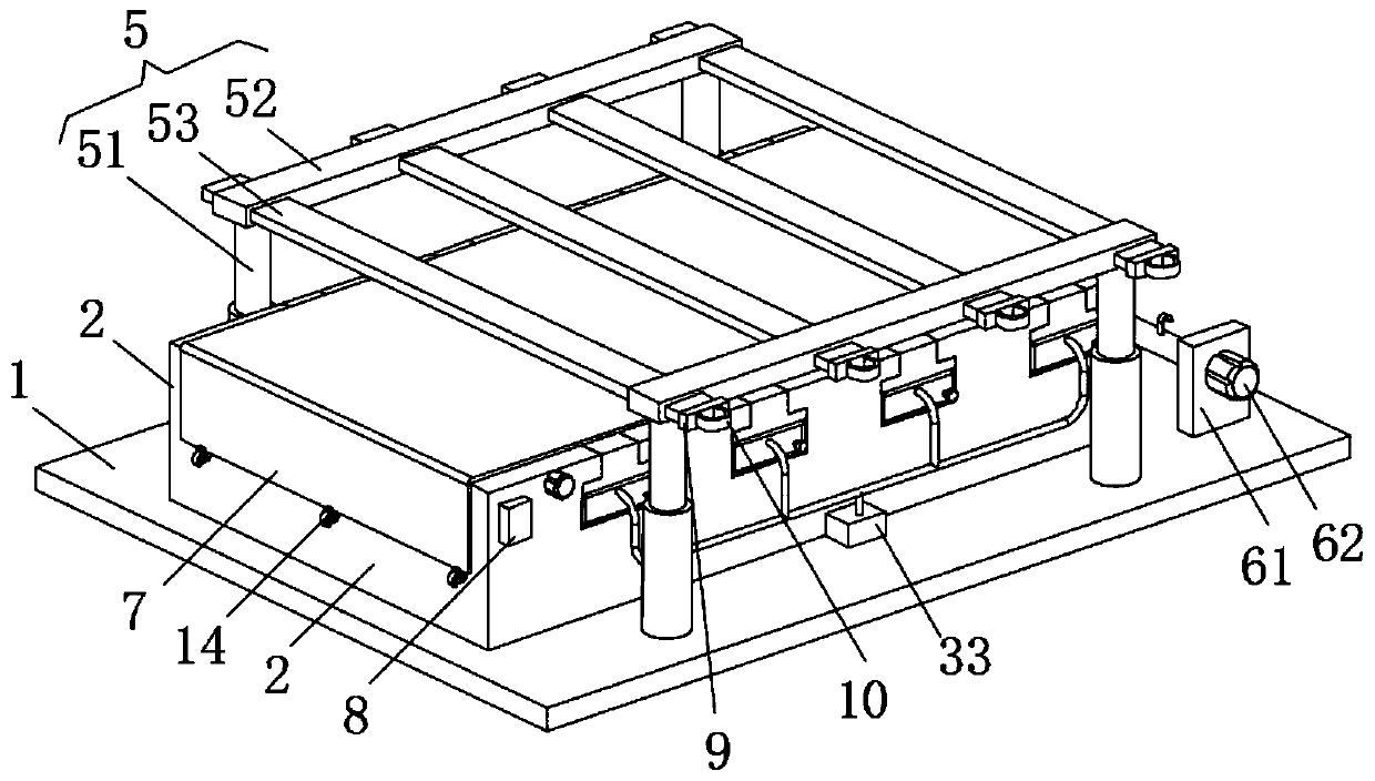
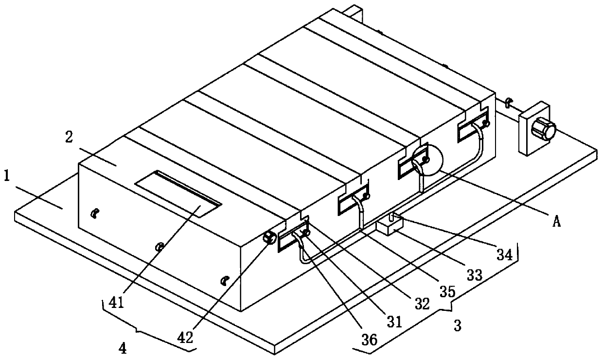
[0021] Embodiment 1: A family hospital bed for easy bed sheet replacement, including a bottom plate 1 , a support unit 3 , an adjustment unit 4 , a moving unit 5 , a connection unit 6 and a control switch group 8 .

[0022] The upper surface of the bottom plate 1 is fixed with a mounting platform 2, the support unit 3 is installed on the upper surface of the mounting platform 2, and the adjustment unit 4 is installed at one end of the upper surface of the mounting platform 2; a bed sheet 7 is placed on the upper surface of the mounting platform 2, and the control switch group 8 is arranged on the side of the installation platform 2, to control the electric telescopic rod 51 of the mobile unit 5;

[0023] The mobile unit 5 includes an electric telescopic rod 51, a connecting block 52 and a support plate 53. There are multiple electric telescopic rods 51, four as shown in the figure, and the four electric telescopic rods 51 are correspondingly installed on the upper surface of th...

Embodiment 2

[0033] The difference between this embodiment and Embodiment 1 is:

[0034] In this embodiment, a limiting block 9 is arranged on the right side of the supporting plate 53 , and a pull ring 10 is arranged on the limiting block 9 .

[0035] Specifically, in this way, the movement range of the support plate 53 is limited by setting the limit block, and the setting of the pull ring 10 can pull out the support plate 53 very conveniently.

Embodiment 3

[0037] The difference between this embodiment and Embodiment 1 is:

[0038] Figure 5 It is a structural schematic diagram of the hook 14 in another embodiment of the present invention. In this example, if Figure 5 As shown, the hospital bed also includes: connecting rings 13 on the matching bed sheet 7 , and hooks 14 correspondingly connected to the connecting rings 13 are fixed on the left and right sides of the installation platform 2 .

[0039] A bed sheet 7 is placed on the upper surface of the installation platform 2, and six corresponding connecting rings 13 are fixed on the left and right sides of the bed sheet 7, and six corresponding hooks 14 are fixed on the left and right sides of the installation platform 2, and the connecting rings 13 are connected to the hooks. 14 snap together.

[0040] Specifically, it is set in this way that the bed sheet 7 is fixed by setting the connecting ring 13 and the hook 14 .

[0041] When in use: the four support plates 53 are e...


PUM


Abstract

The invention discloses a home sick-bed with convenient replacement of bed sheets. The home sick-bed with convenient replacement of bed sheets includes a bottom plate, a support unit, an adjusting unit, a moving unit, a connecting unit and a control switch group, wherein a mounting table is fixed to the upper surface of the bottom plate, the support unit is mounted on the upper surface of the mounting table, and the adjusting unit is mounted on one end of the upper surface of the mounting table; and the control switch group is arranged on the side surface of the mounting table, and is used forcontrolling an electric telescopic rod of the moving unit. A patient is driven to move through arrangement of the moving unit, the support unit is installed on the upper side surface of the mountingtable, cooperation is formed between the support unit and the moving unit, and the patient is supported by the support unit, so that the bed sheets are replaced very conveniently.

Description

technical field [0001] The invention relates to the technical field of family sick beds, in particular to a family sick bed which is convenient for changing bed sheets. Background technique [0002] The family bed is designed according to the patient's treatment needs and bed-ridden living habits, and uses the home as a treatment and nursing place to assist the patient's recovery. It can meet the various needs of treatment, rehabilitation and nursing. When existing family beds are used for nursing care of paralyzed patients and serious patients who have lost their ability to take care of themselves, the nursing work is laborious and time-consuming. If the patient needs to change the bed sheet, the patient needs to be lifted from the bed and then replaced. This process often requires Many people operate, very troublesome, and may cause injury to the patient. Contents of the invention [0003] The technical problem to be solved by the present invention is to overcome the ex...

Claims


Application Information

Patent Timeline
IPC IPC(8): A61G7/012A61G7/10
CPCA61G7/012A61G7/1019A61G7/1073
Inventor 孙小叶
Owner SHAOYANG UNIV
Why Eureka
Try Eureka