Flowmeter support welding fixture

A technology for welding tooling and flowmeters, applied in welding equipment, auxiliary welding equipment, welding/cutting auxiliary equipment, etc., can solve problems such as low production efficiency, inability to solve mass production of flowmeter brackets, and reduced product productivity.

Pending Publication Date: 2020-07-07
SUZHOU FENGSHI SHEET METAL
View PDF0 Cites 0 Cited by
  • Summary
  • Abstract
  • Description
  • Claims
  • Application Information

AI Technical Summary

Problems solved by technology

[0002] The flowmeter bracket is particularly important as a support frame to support the flowmeter probe. The flowmeter brackets currently used in the market are basically one-piece, permanently fixed brackets, which are very heavy and difficult to disassemble.
[0003] The welding process in the production process of the existing f

Method used


Image

  • Flowmeter support welding fixture
  • Flowmeter support welding fixture
  • Flowmeter support welding fixture

Examples


Embodiment 1

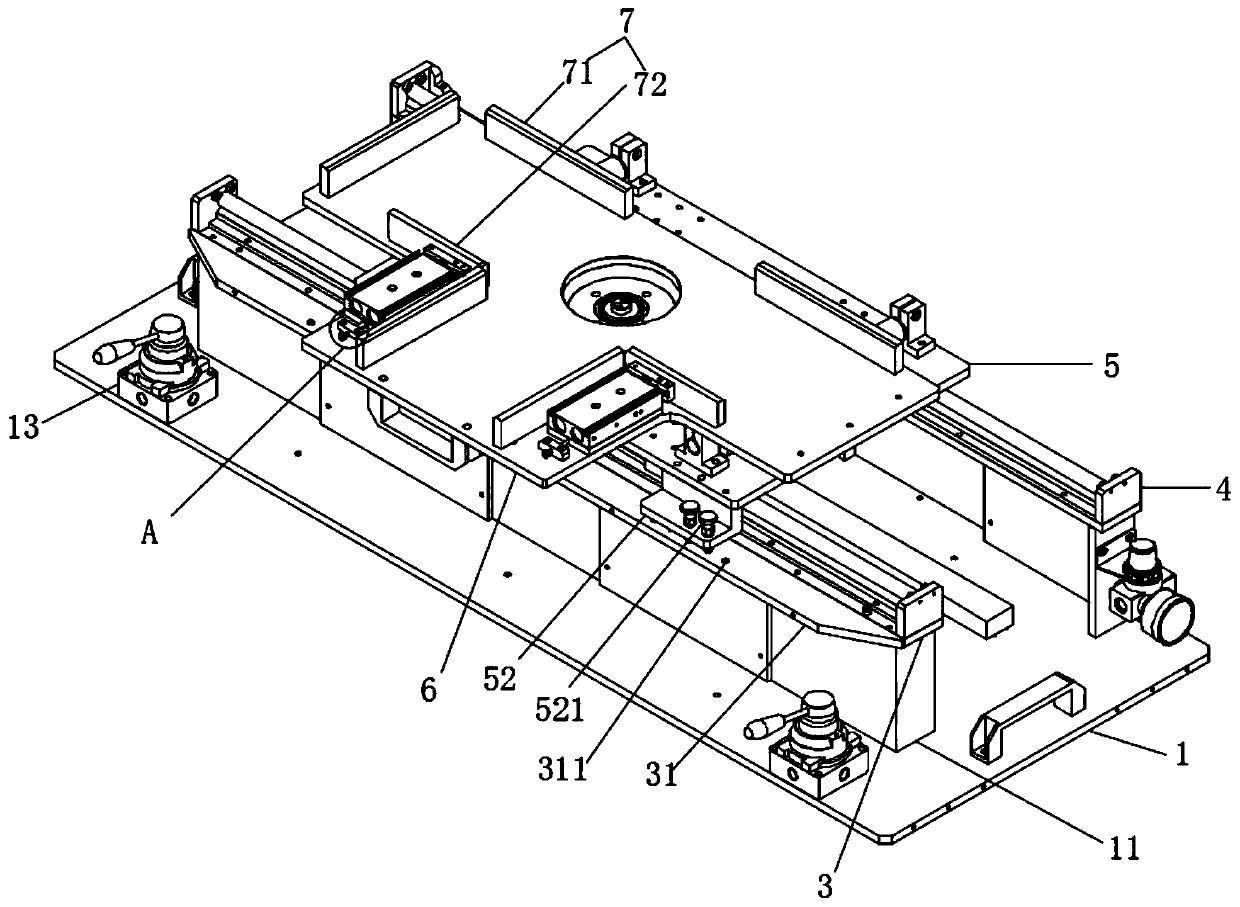
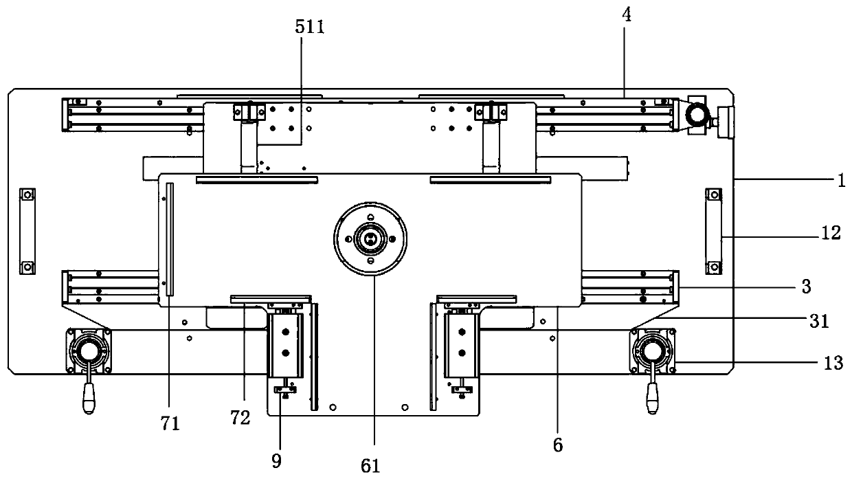
[0025] see Figure 1 to Figure 5 , the figure shows a flowmeter bracket welding tool provided by Embodiment 1 of the present invention, mainly provided with a bottom plate 1, and supporting plates 11 are respectively arranged on both sides of the bottom plate 1, and the two supporting plates 11 are arranged in parallel along the length direction of the bottom plate 1 , the first slide rail 3 and the second slide rail 4 are respectively arranged on the two supporting plates 11, the first slide rail 3 and the second slide rail 4 are slidably connected with the slide seat 5, and the slide seat 5 is provided with two parallel first slide rails. Three slide rails 51, two third slide rails 51 are slidably connected with a positioning plate 6, the positioning plate 6 is T-shaped at a top view angle, and the positioning plate 6 is provided with several limiting plates 7, and several limiting plates 7 are arranged along the The circumferential direction of the positioning plate 6 is ar...

Embodiment 2

[0033] see Figure 1 to Figure 5 , the figure shows a flowmeter bracket welding tool provided by Embodiment 2 of the present invention. On the basis of the above-mentioned embodiments, this embodiment further makes the following technical solutions as improvements: the first slide rail 3 A fixed plate 31 extends outward from one side of the fixed plate 31 , and a plurality of positioning holes 311 are opened on the fixed plate 31 , and the plurality of positioning holes 311 are arranged along the length direction of the fixed plate 31 . The fixing plate is integrated with the base of the first slide rail, which is convenient for installation, and the positioning hole is a screw hole, which can fix the slide seat after the slide seat is adjusted, thereby improving the welding quality. The two ends of the fixed plate have bevels, which can provide the operation space of the pneumatic clamp.

Embodiment 3

[0035] see Figure 1 to Figure 5 , the figure shows a flowmeter bracket welding tool provided by the third embodiment of the present invention. This embodiment further makes the following technical solutions as improvements on the basis of the above-mentioned embodiments: the sliding seat 5 is close to the first One side of a slide rail 3 is provided with at least one fixing block 52 , and a fixing rod 521 matching the positioning hole 311 is detachably connected to the fixing block 52 . The cross section of the fixing block 51 is L-shaped. The fixed rod is a screw rod, so that the fixed rod matches the positioning hole, so that the fixed rod can be easily disassembled, so that the position of the positioning plate can be adjusted conveniently, and the work efficiency can be improved. Moreover, the bottom of the L-shaped fixing block can resist the slide rail, and can also play the role of supporting the slide seat.


PUM


Abstract

The invention provides a flowmeter support welding fixture. The flowmeter support welding fixture comprises a base plate. Supporting plates are arranged on the two sides of the base plate correspondingly. The two supporting plates are arranged in parallel in the length direction of the base plate. A first sliding rail and a second sliding rail are arranged on the two supporting plates separately and further connected with a sliding base in a sliding mode. Two parallel third sliding rails are arranged on the sliding base. The two third sliding rails are connected with a positioning plate in a sliding mode, and the positioning plate is in a T shape at the overlooking angle and is provided with a plurality of limiting plates. The multiple limiting plates are arranged in the circumferential direction of the positioning plate. A limiting groove matched with a flowmeter support in contour is formed in the center of the positioning plate. Compared with the prior art, the flowmeter support welding fixture can achieve mechanical automation of flowmeter support welding, the labor intensity of workers is relieved and the production rate of products is increased.

Description

technical field [0001] The invention relates to a welding tool, in particular to a flow meter support welding tool. Background technique [0002] The flowmeter bracket is particularly important as a support frame for supporting the flowmeter probe. The flowmeter brackets currently used in the market are basically one-piece, permanently fixed brackets, which are very heavy and difficult to disassemble. [0003] The welding process in the production process of the existing flowmeter bracket usually requires manual welding, the production efficiency is low, and the mass production problem of flowmeter bracket welding cannot be solved, and the mechanical automation process of flowmeter bracket welding cannot be realized, which reduces the product cost. Productivity increases the labor intensity of workers. Contents of the invention [0004] In view of this, the present invention provides a flowmeter bracket welding tool, which can realize the mechanical automation of the flow...

Claims


Application Information

Patent Timeline
IPC IPC(8): B23K37/04
CPCB23K37/0435
Inventor 冯淑琴
Owner SUZHOU FENGSHI SHEET METAL
Why Eureka
Try Eureka