
Automatic ring belt error polishing numerical control single-shaft equipment and technology method thereof

An endless belt and automatic technology, which is applied in the direction of grinding/polishing equipment, metal processing equipment, workpiece feed movement control, etc., can solve the inconsistency of removal efficiency, uneven rotation of passive grinding discs, and the inability to realize precise machining of endless belts And other issues

Active Publication Date: 2020-07-07
NANJING NAIERSI PHOTOELECTRIC INSTR
View PDF7 Cites 4 Cited by
  • Summary
  • Abstract
  • Description
  • Claims
  • Application Information

AI Technical Summary

Problems solved by technology

The following problems exist in the processing process of the traditional single-axis polishing system: (1) The non-uniformity of the rotational movement of the passive grinding disc leads to inconsistent removal efficiency of the grinding disc at the center and edge of the workpiece; (2) Manual control of the translation axis makes each ring belt The radius and the processing time of each ring cannot be accurately realized, so that the precise processing of the ring cannot be realized

Method used


Image

  • Automatic ring belt error polishing numerical control single-shaft equipment and technology method thereof
  • Automatic ring belt error polishing numerical control single-shaft equipment and technology method thereof
  • Automatic ring belt error polishing numerical control single-shaft equipment and technology method thereof

Examples


Embodiment Construction

[0044] The present invention will be described in further detail below in conjunction with the accompanying drawings.

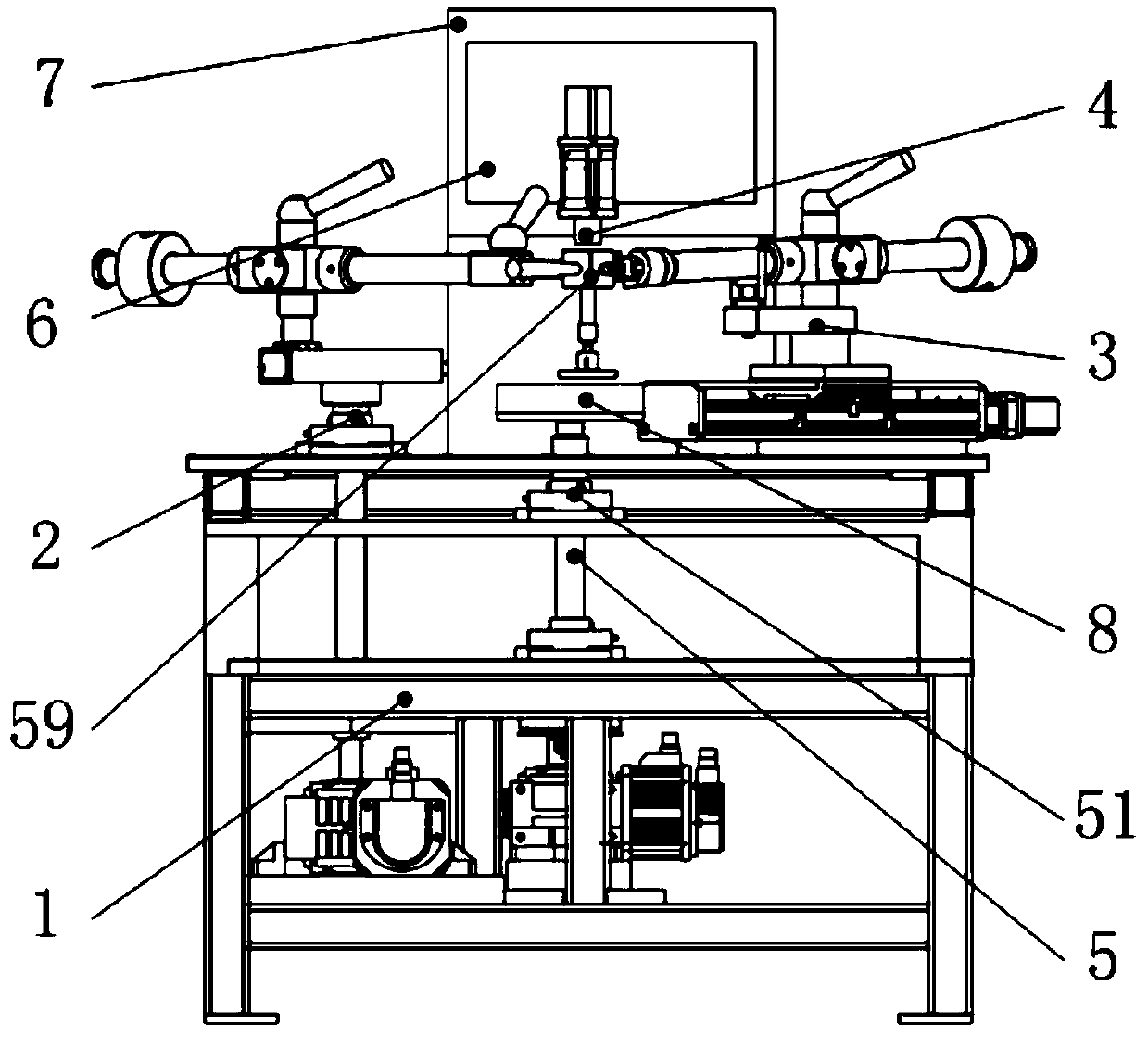
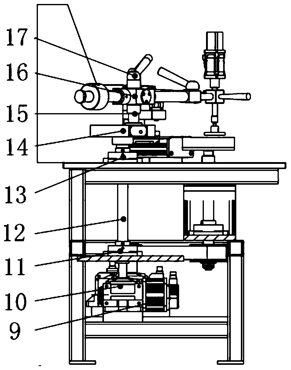
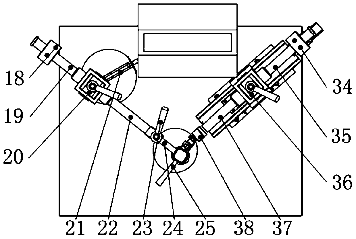
[0045] The structure of the automatic ring belt error polishing numerical control uniaxial equipment of the present invention is as follows figure 1 As shown, it includes: base system 1, swing arm system 2, translation arm system 3, active disc system 4, mirror body rotation system 5, numerical control system 6 and electric control cabinet 7. Based on the traditional manual single-axis polishing machine, starting from the controllable constant speed rotation of the grinding disc and the numerical control movement of the translation axis, through numerical control, the automatic removal of the fixed ring belt of the workpiece material is realized, and the ring belt processing, uniform removal, and Smooth etc. The specific structure of each system is as follows:

[0046] Base system 1: Base system 1 is the base of the CNC single-axis polishing machine. The s...


PUM


Abstract

The invention discloses automatic ring belt error polishing numerical control single-shaft equipment and a technology method thereof. The equipment comprises a base system, a swing arm system, a translation arm system, a driving milling disc system, a lens body rotating system and a numerical control system. A milling disc fixing block is arranged on the connecting portion of the swing arm systemand the translation arm system. The driving milling disc system is installed at the position of a center hole of the milling disc fixing block. By adjusting the clamping height of a milling disc, a swing arm of the swing arm system and a translation arm of the translation arm system are in a horizontal state, the swing arm system enables the center hole of the driving milling disc fixing block tocoincide with the center of a lens body to be machined when the swing arm is horizontal through eccentric adjustment of an eccentric adjusting mechanism and swing arm rod length adjusting of a swing arm rod length adjusting mechanism, the numerical control system controls the rotating speed of the lens body to be machined, the rotating speed of the milling disc and the motion amount of a translation shaft, and pressure of the milling disc is adjusted by adjusting the hammer position of the swing arm and the translation arm. According to the equipment, automatic machining of ring belt error uniform removing and smoothing can be achieved, the machining efficiency is improved, and the machining cost is saved.

Description

technical field [0001] The invention belongs to the field of optical processing, and relates to an optical mirror annular band numerical control single-axis processing equipment and a processing technology, in particular to an automatic annular band error polishing numerical control single-axis equipment and a process method thereof. Background technique [0002] In the process of optical mirror surface processing, it is necessary to process the specified ring belt of the mirror surface, or uniformly remove the material of the mirror surface, remove the damaged layer material on the surface of the workpiece with equal thickness, and smooth the processed surface. As a traditional processing equipment, the traditional single-axis polishing machine has the characteristics of simple application, high processing efficiency, and rotationally symmetrical processing. It can realize the processing of ring belts, but it cannot realize quantitative numerical control processing, and its ...

Claims


Application Information

Patent Timeline
Patent Type & Authority Applications(China)
IPC IPC(8): B24B13/00B24B13/005B24B49/00B24B49/16B24B49/12B24B41/047B24B27/02
CPCB24B13/0018B24B13/0055B24B27/02B24B41/047B24B49/006B24B49/12B24B49/165
Inventor 焦长君张真王斌何家桥宫萌汪德峰王波
Owner NANJING NAIERSI PHOTOELECTRIC INSTR
Learn More