Eureka AIR delivers breakthrough ideas for toughest innovation challenges, trusted by R&D personnel around the world.

Flying wing configuration drone aircraft invisibility control surface mounting structure

A technology of installation structure and rudder surface, applied in aircraft parts, aircraft control, target and other directions, can solve the problem of not meeting the requirements of stealth

Pending Publication Date: 2020-07-07
AEROSPACE SHENZHOU AIRCRAFT
View PDF0 Cites 6 Cited by
  • Summary
  • Abstract
  • Description
  • Claims
  • Application Information

AI Technical Summary

Problems solved by technology

In order to ensure its good stealth performance, it is necessary to reduce or avoid protrusions on the bottom of the fuselage. Among the target drones on the market, the target drone with flying wing layout has good stealth performance. The resistance rudder surface of flying wing layout is in the It plays the role of rudder during flight, so the design of the installation structure is particularly important. It must be stable and stealthy. Most of the rudder surface executive rods on the market are mostly exposed new types, which have a large reflective surface for RCS testing. , does not meet the stealth requirements, so it is imperative to realize the stealth rudder surface

Method used


Image

  • Flying wing configuration drone aircraft invisibility control surface mounting structure
  • Flying wing configuration drone aircraft invisibility control surface mounting structure
  • Flying wing configuration drone aircraft invisibility control surface mounting structure

Examples


Embodiment Construction

[0027] In order to make the technical means, creative features, goals and effects achieved by the present invention easy to understand, the present invention will be further described below in conjunction with specific embodiments.

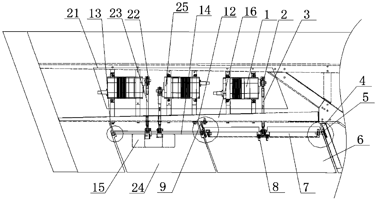
[0028] see Figure 1 to Figure 6 , the present invention provides a technical solution: a stealth rudder surface installation structure of a flying wing layout target aircraft, including an aileron unit and a resistance rudder unit, and the aileron unit includes an aileron steering gear 1, a steering gear rocker arm-2 , steering gear connecting rod one 3, oblique rib 4, right side support seat 5, steering surface 6 and left side connecting seat 9, described steering gear connecting rod one 3 such as image 3 As shown, the steering gear connecting rod one 3 includes a connecting rod main body 17 and a nut 18, and the two ends of the connecting rod main body 17 are respectively threaded with rod-end joint bearings 19 with opposite helical directions...


PUM


Abstract

The invention provides a flying wing configuration drone aircraft invisibility control surface mounting structure. The flying wing configuration drone aircraft invisibility control surface mounting structure comprises an auxiliary wing unit and a resistance direction rudder unit, the auxiliary wing unit comprises an auxiliary wing steering engine, a first steering engine rocker arm, a first steering engine connecting rod, an inclined rib, a right side supporting base, a control surface and a left side connecting base, the resistance direction rudder unit comprises two resistance direction rudder steering engines, a second steering engine rocker arm, a second steering engine connecting rod, a resistance direction rudder upper control surface, a resistance direction rudder lower control surface, a right side mounting base, a left side mounting base, a transverse shaft, a resistance direction rudder pull base and a stabilizing plane rear beam, and the flying wing configuration drone aircraft invisibility control surface mounting structure is reasonable in design, capable of enabling the lower surface of an aircraft to be free of convex objects, small in reflection area during radar irradiation, capable of achieving the invisibility function and in addition capable of enabling the control surface to be detachable and convenient to maintain.

Description

technical field [0001] The invention relates to the technical field of high-speed target drones, in particular to a stealth rudder surface installation structure of a flying-wing layout target drone. Background technique [0002] In the military field, the target drone is a necessary equipment for testing the pros and cons of weapons. It has always played an important role in radar testing and missile testing. a key indicator of . In order to ensure its good stealth performance, it is necessary to reduce or avoid protrusions on the bottom of the fuselage. Among the target drones on the market, the target drone with flying wing layout has good stealth performance. The resistance rudder surface of flying wing layout is in the It plays the role of rudder during flight, so the design of the installation structure is particularly important. It must be stable and stealthy. Most of the rudder surface executive rods on the market are mostly exposed new types, which have a large ref...

Claims


Application Information

Patent Timeline
IPC IPC(8): F41J9/08B64C9/02
CPCB64C9/02F41J9/08
Inventor 姜明泽王亚龙
Owner AEROSPACE SHENZHOU AIRCRAFT
Why Eureka
Eureka Blog
Learn More