
Manufacturing process of periscopic camera module shell

A technology of camera module and manufacturing process, applied in metal material coating process, vacuum evaporation coating, coating, etc., can solve problems affecting user experience, high requirements, unsatisfactory, etc., to suppress the generation of stray light , Low reflectivity, reduce reflection effect

Active Publication Date: 2022-06-28
GUANG DONG YUPIN IND CO LTD
View PDF12 Cites 0 Cited by
  • Summary
  • Abstract
  • Description
  • Claims
  • Application Information

AI Technical Summary

Problems solved by technology

In order to reduce the reflectivity of the light hole and internal blackening, the existing technology generally prints black through the silk screen process, but the reflectivity of the shell in the prior art is relatively high in the 400-800nm ​​light band, and generally can only reach less than or equal to 2%. , and there will be more stray light, so that the image quality and definition of the camera cannot meet people's higher and higher requirements, and affect the user experience

Method used


Image

  • Manufacturing process of periscopic camera module shell
  • Manufacturing process of periscopic camera module shell
  • Manufacturing process of periscopic camera module shell

Examples


Embodiment Construction

[0030] The technical solutions in the embodiments of the present invention will be clearly and completely described below with reference to the accompanying drawings in the embodiments of the present invention. Obviously, the described embodiments are only a part of the embodiments of the present invention, but not all of the embodiments. Based on the embodiments of the present invention, all other embodiments obtained by those of ordinary skill in the art without creative work fall within the protection scope of the present invention.

[0031] It should be noted that all directional indications (such as up, down, left, right, front, back, etc.) in the embodiments of the present invention are only used to explain the relative relationship between various components under a certain posture (as shown in the accompanying drawings). If the specific posture changes, the directional indication also changes accordingly.

[0032] In addition, the descriptions involving "first", "secon...


PUM

PropertyMeasurementUnit
thicknessaaaaaaaaaa
thicknessaaaaaaaaaa
reflectanceaaaaaaaaaa

Abstract

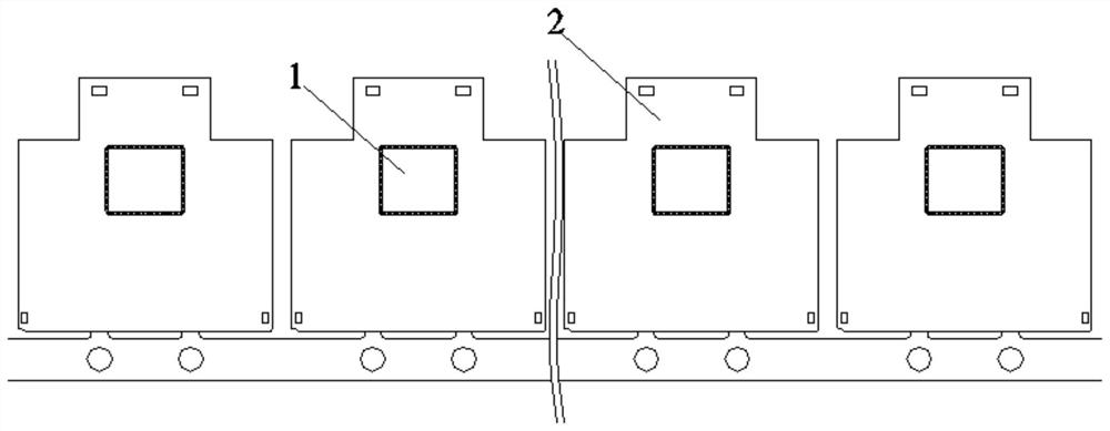
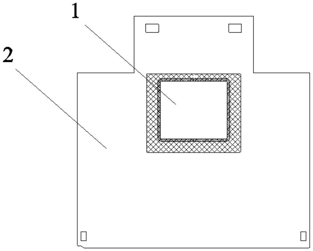
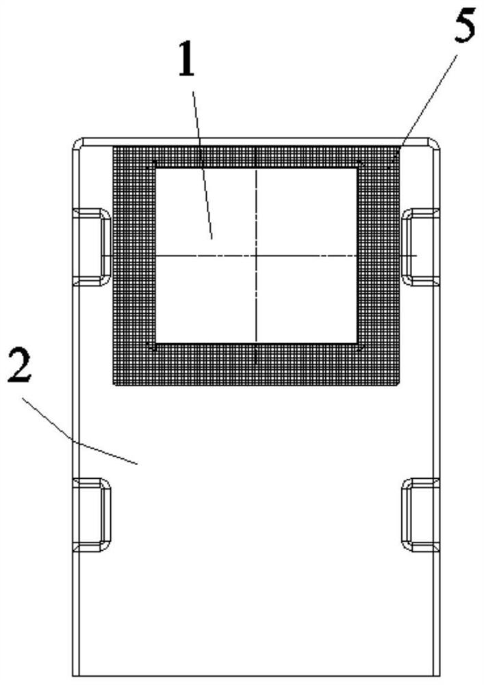
The invention belongs to the technical field of camera modules, and particularly relates to a manufacturing process of a periscopic camera module shell, which at least comprises the following steps: etching: placing a base material subjected to coating, exposure and development treatment in an etching solution for etching treatment to obtain a substrate with a light through hole, and forming a chamfer structure on the inner side edge of the light through hole; film plating: plating an absorbing film layer on the substrate by adopting a plasma sputtering film plating process, and in the film plating process, shielding a non-film-plating region by using a jig, so that the absorbing film layers are attached to the film plating region and the chamfering structure; bending is conducted, specifically, stamping and bending operation is conducted on the coated substrate, and a shell frame is obtained; and the shell frame obtained in the third step is subjected to laser welding, and the needed shell is obtained. Compared with the prior art, light reflection of the light through hole can be reduced to the maximum extent under the dual effects of reducing the reflection area and reducing the reflectivity, so that stray light is inhibited, the thickness of the film layer is small and controllable, and the image quality and definition of the camera are improved.

Description

technical field [0001] The invention belongs to the technical field of camera modules, and in particular relates to a manufacturing process of a periscope camera module shell. Background technique [0002] At present, terminal devices with camera functions have become indispensable electronic products in people's work and life, such as smart phones and tablet computers. The increasing demand for cameras in smartphones and tablet computers makes the camera one of the important core components of smartphones and tablet computers. [0003] A periscope camera is a camera with a special structure designed for shooting distant objects. Its main characteristics are long focal length and small viewing angle. It can achieve clear shooting for long-distance targets. It usually includes camera components and reflectors. , the external natural light is reflected by the mirror and then imaged on the camera assembly. The camera assembly needs to use a housing assembly, which contains a ...

Claims


Application Information

Patent Timeline
Patent Type & Authority Applications(China)
IPC IPC(8): B23P15/00C23C14/04C23C14/10C23C14/16C23C14/34C23F1/02C23F1/28
CPCB23P15/00C23F1/28C23F1/02C23C14/042C23C14/34C23C14/165C23C14/10
Inventor 席龙龙席冬冬
Owner GUANG DONG YUPIN IND CO LTD
Learn More