
A signal control device, method and vehicle

A signal control and signal technology, applied in the field of control, can solve problems such as the straight-through of the upper and lower bridge arms

Active Publication Date: 2021-10-01
HYCET TRANSMISSION SYST (JIANGSU) CO LTD BAODING RES & DEV BRANCH
View PDF8 Cites 0 Cited by
  • Summary
  • Abstract
  • Description
  • Claims
  • Application Information

AI Technical Summary

Problems solved by technology

[0004] In view of this, the present invention aims to propose a signal control device, method and vehicle to solve the problem in the prior art that there is still a direct connection between the upper and lower bridge arms caused by setting the dead time

Method used


Image

  • A signal control device, method and vehicle
  • A signal control device, method and vehicle
  • A signal control device, method and vehicle

Examples


Embodiment Construction

[0048] It should be noted that, in the case of no conflict, the embodiments of the present invention and the features in the embodiments can be combined with each other. The present invention will be described in detail below with reference to the accompanying drawings and examples.

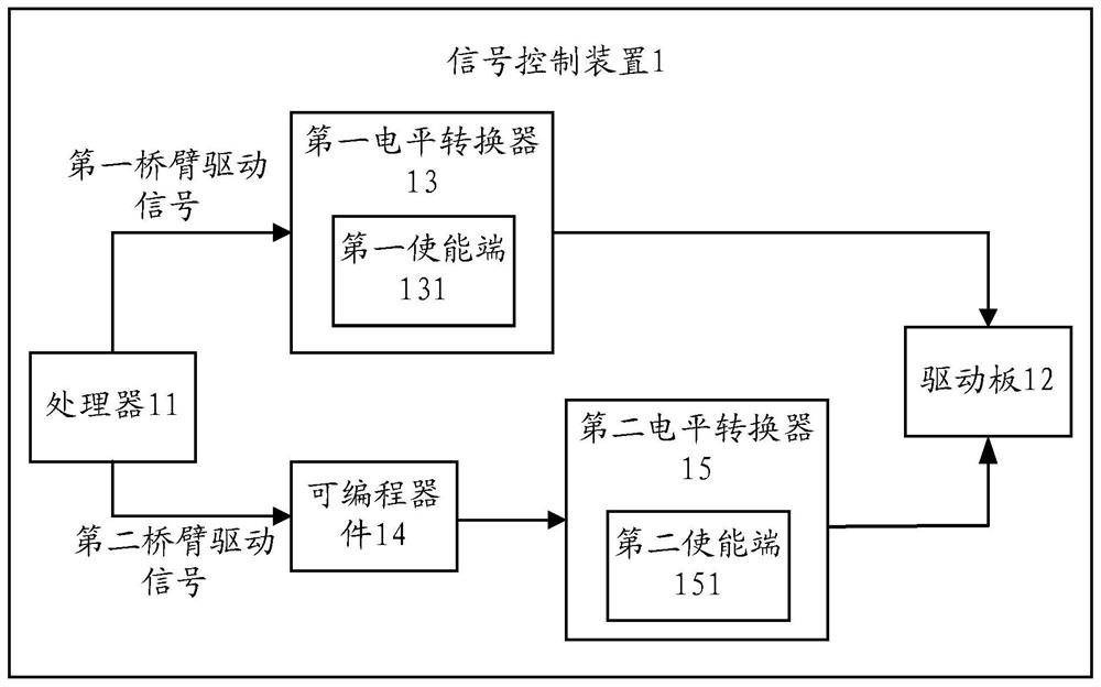
[0049] figure 1 A signal control device 1 shown in an embodiment of the present invention, such as figure 1 As shown, the signal control device 1 includes:

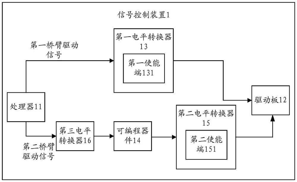
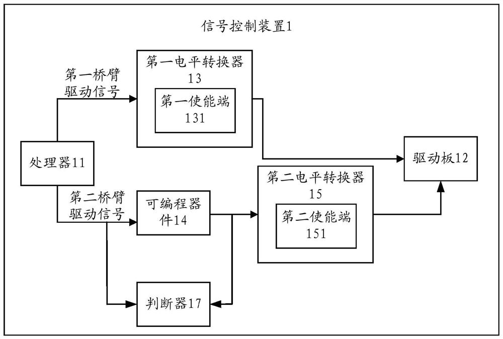
[0050] A processor 11 for sending out a first bridge arm driving signal and a second bridge arm driving signal, a driving board 12 for sending out a driving fault signal, and a first parallel arrangement between the processor 11 and the driving board 12 A level shifter 13 and a programmable device 14, a second level shifter 15 arranged between the programmable device 14 and the drive board 12, wherein the first level shifter 13 includes a first enable terminal 131 , the second level shifter 15 includes a second enabling terminal 151 .

...


PUM


Abstract

The present invention provides a signal control device, a method and a vehicle, the device includes: a processor for sending a first bridge arm drive signal and a second bridge arm drive signal, a drive board for sending a drive failure signal, and The first level shifter and the programmable device arranged in parallel between the processor and the driver board, and the second level shifter arranged between the programmable device and the driver board; wherein, the first level shifter includes the second An enabling terminal, the second level converter includes the second enabling terminal; when the first enabling terminal is in an on state, the driving signal of the first bridge arm is transmitted to the driving board through the first level converter; When the two enable ends are in the open state, the drive signal of the second bridge arm is transmitted to the drive board through the programmable device and the second level shifter in sequence; when the processor receives the fault signal of the first bridge arm sent by the drive board, it passes The processor or the programmable device controls the first enabling terminal to switch to an off state.

Description

technical field [0001] The invention relates to the technical field of control, in particular to a signal control device, method and vehicle. Background technique [0002] With the development of new energy vehicles, the core issue at present is the driving motor technology, that is, the driving technology of the motor controller. In the driving motor technology, the control of the PWM (Pulse Width Modulation; Pulse Width Modulation) signal sent from the MCU (Microcontroller Unit; Microcontroller Unit) is particularly important. [0003] At present, most of the driving motor technology adopts the direct drive type, that is, the PWM signal sent by the MCU is directly transmitted to the driver board. Considering the occurrence of the upper and lower bridge arms through-through, the software dead-time is generally set to avoid the occurrence of the upper and lower bridge arm through-through phenomenon. However, the existing dead time is a preset fixed value, which cannot monit...

Claims


Application Information

Patent Timeline
Patent Type & Authority Patents(China)
IPC IPC(8): G05B19/042
CPCG05B19/0423G05B2219/24215
Inventor 高瑞娟刘浩任卫红张雪王振达
Owner HYCET TRANSMISSION SYST (JIANGSU) CO LTD BAODING RES & DEV BRANCH
Learn More