Method for assembling a water pump

A technology of water pumps and pump wheels, which is applied in the field of assembling water pumps and can solve problems such as loss of rare earth metals

Active Publication Date: 2020-07-07
HANON SYST EFP DEUT GMBH
View PDF7 Cites 1 Cited by
  • Summary
  • Abstract
  • Description
  • Claims
  • Application Information

AI Technical Summary

Problems solved by technology

However, the use of rare earth metals suffers from losses due to fluids such tha

Method used


Image

  • Method for assembling a water pump
  • Method for assembling a water pump
  • Method for assembling a water pump

Examples


Embodiment Construction

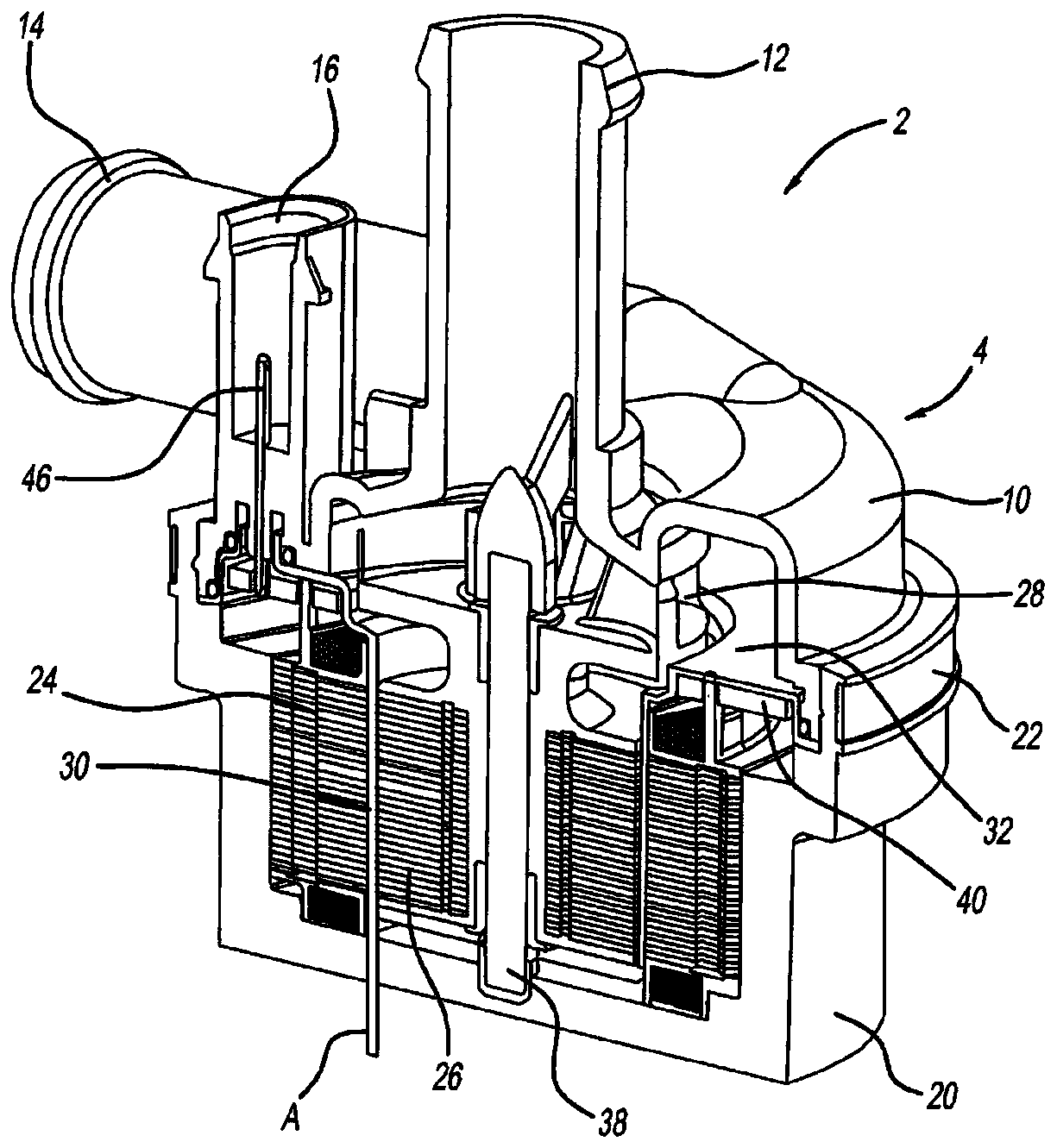
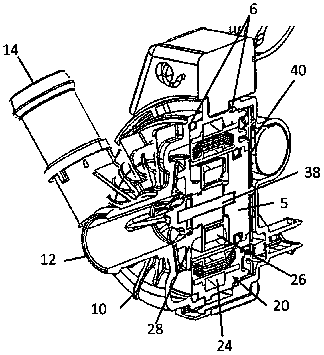
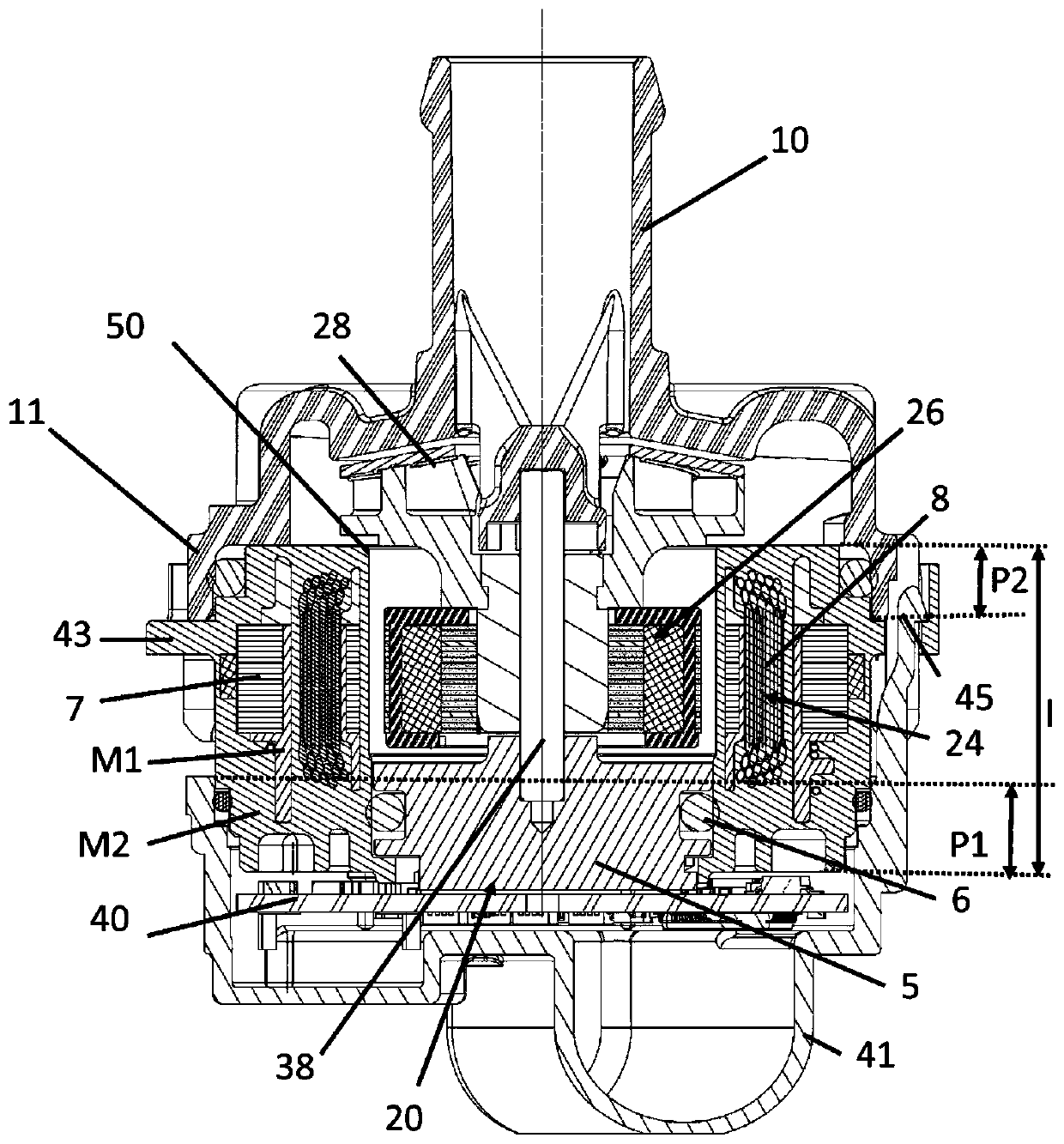
[0017] The water pump 2 comprises a screw housing 10 , a collar 20 and a band 22 which fixes the collar 20 and the screw housing 10 . The spiral housing 10 includes an inlet 12 and an outlet 14 . The screw housing includes current supply terminals 16 . The spiral housing 10 is connected to a collar 20 by means of a strap 22 and forms a cover 4 which surrounds the inner components and encloses the current supply connection 16 for accommodating a current supply line 46 . The internal components of the housingless water pump 2 include the stator 24 which is pressed into the collar 20 . A stator 24 surrounds a rotor 26 . The rotor 26 is separated from the stator 24 by a wet bush. The rotor 26 and the stator 24 are separated by a distance (A) by a magnetic air gap. Wet liner 30 prevents fluid from contacting stator 24 . The rotor 26 includes a shaft 38 and an impeller 28 for moving the fluid as it enters through the inlet 12 . The impeller 28 moves fluid through the outlet 14...


PUM


Abstract

The invention relates to a method for assembling a water pump (2) having an impeller (28), driven by an electrical machine, the water pump comprising a housing cover (41), a spiral housing (10), whichhas an inlet (12) and an outlet (14), a sleeve (20), in which a stator (24) and a rotor (26) of the electrical machine are accommodated, and an electronic circuit board (40), which is mounted on theside away from the pump wheel (28) and is covered by the cover housing (41), the sleeve (20) having a radially extending edge (43), which comprises at least slits (44), said method being defined by the following steps: connecting the spiral housing (10) to the sleeve (20) by inserting axial hooks (11) into the slits (44) of the sleeve, rotating the spiral housing (10) relative to the sleeve (20) in order to fasten the axial hooks (11), inserting radial hooks (45) of the cover housing (41) into the same slits (44).

Description

technical field [0001] The invention relates to a method of assembling a water pump having a pump wheel driven by an electric motor, the water pump comprising: a housing cover and a helical housing with an inlet and an outlet; a collar, the stator of the motor and the rotor accommodated in the collar; and an electronic circuit board mounted on the side facing away from the pump wheel and covered by the cover housing, wherein the stator laminations are cast over. Background technique [0002] Generally, a water pump includes a stator and a rotor. The rotor is connected to the impeller to move the fluid. Fluid enters the pump through an inlet in the helical housing, contacts the impeller, and moves through an outlet in the helical housing. The rotor and stator are contained in a casing connected to the helical casing. Typically, the rotor and stator are separated by a magnetic air gap, and the rotor and stator include rare earth metals, so that the magnetic air gap between ...

Claims


Application Information

Patent Timeline
IPC IPC(8): F04D13/06F04D29/62F04D29/42
CPCF04D13/0653F04D13/0686F04D29/426F04D29/628F05D2260/36F04D13/0693F05D2210/11F04D13/06F04D29/086F04D29/5893
Inventor 埃内斯托·乔瓦尼·阿诺尔迪保罗·林科尔恩·毛里诺
Owner HANON SYST EFP DEUT GMBH
Why Eureka
Try Eureka