Soil loosening device mounted on agricultural vehicle

A technology for agricultural vehicles and soil loosening, applied in the application, agriculture, agricultural machinery and implements, etc., can solve the problems of low degree of automation, inconvenient operation, loose soil, etc. large area effect

Inactive Publication Date: 2020-07-10
CHANGZHOU COLLEGE OF INFORMATION TECH
View PDF1 Cites 0 Cited by
  • Summary
  • Abstract
  • Description
  • Claims
  • Application Information

AI Technical Summary

Problems solved by technology

[0003] When the existing devices are in use, the speed of loosening the soil and leveling the ground at the same time is relatively slow, and the loosening effect is low. Some devices are relatively large, inconvenient to operate and inconvenient to transport, and some devices are driven by a motor. , when loosening and grinding are carried out at the same time, the speed is slow, and the effect is not good, which affects the use of the user, wastes the user's time, and reduces the work efficiency
[0004] The soil loosening device with the application number 201811463018.X includes a rotating housing, and soil turning wheels are arranged on both sides of the rotating housing, and a set block is arranged between the turning wheel and the rotating housing. It is fixed on the outer wall of the rotating housing, and a connecting rod is sleeved inside the sleeve, and a scraper is fixed on the bottom of the connecting rod, and a groove is opened on one side of the outer wall of the connecting rod, and the groove is connected with a stopper by sliding , the stopper is fixed on the inner wall of the cover block; the present invention has a low degree of automation, and only uses the scraper to loosen the soil, which has poor effect, and the contact surface between the scraper and the land is large, so it is easy to move the soil, causing unevenness in the land , is not conducive to the later planting work, the scraper acts on the soil, and it only removes a large piece of soil, and does not substantially loosen the soil

Method used


Image

  • Soil loosening device mounted on agricultural vehicle
  • Soil loosening device mounted on agricultural vehicle

Examples


Embodiment Construction

[0016] The preferred technical solutions of the present invention will be described in detail below in conjunction with the accompanying drawings.

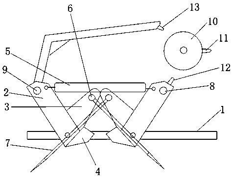
[0017] A soil loosening device installed on an agricultural vehicle is characterized in that it comprises a rectangular frame 1, and two swinging parts are respectively installed on the outer sides of a group of opposite sides of the frame 1, and the swinging parts include a swinging part 2, a sliding part 3. Limiting part 4, one end of the swing part 2 is rotatably connected to the frame 1, the sliding part 3 is vertically connected to the swing part 2, and the sliding part 3 is located near the rotational connection position between the swing part 2 and the frame 1. The limit part 4 is located at the position where the swing part 2 is connected to the frame 1 in rotation; the sliding parts 3 of the two swing parts on the same side of the frame 1 are arranged oppositely, and a tension spring 5 is arranged between the other ends of...


PUM


Abstract

The invention discloses a soil loosening device mounted on an agricultural vehicle. The soil loosening device comprises a rectangular frame, wherein two swinging components are respectively mounted onthe outer sides of a group of opposite sides of the frame; the swinging components comprise swinging parts, sliding parts and limiting parts; one end of each swinging part is rotationally connected with the frame; the sliding parts are perpendicularly connected with the swinging parts; the limiting parts are positioned in positions where the swinging parts are rotationally connected with the frame; the sliding parts of two swinging components on a same side of the frame are oppositely arranged; a tension spring is arranged between the other ends of the two swinging parts; connecting rods arearranged between the swinging components and the swinging components which are arranged in a same directions front and back on opposite sides of the frame; a plurality of soil loosening nail mechanisms are arranged on the connecting rods; first driving rods are arranged between the two swinging components in directions close to the agricultural vehicle; and a telescopic driving component for connecting a first driving rod is arranged on the agricultural vehicle. The soil loosening device is capable of turning over soil along with the agricultural vehicle in a field and is good in soil turnovereffect, rapid in speed and large in oil turnover area, and the time can be saved.

Description

technical field [0001] The invention relates to a soil loosening device installed on an agricultural vehicle, belonging to the technical field of agricultural equipment. Background technique [0002] The ripper has a replaceable working device with crushing and scarifying functions. It is divided into rippers for excavators and rippers for bulldozers. The rippers for excavators are also called bucket hooks, and the rippers for bulldozers are also called tail hooks. They are generally single teeth, and there are also two or three teeth, which have strong digging cutting force. An integrally cast loosening tooth with ear holes on the upper part is hinged with the arm and the bucket cylinder respectively. There is a hard alloy surfacing tooth cap at the front end of the tooth tip. When the piston rod of the hydraulic cylinder is extended, the tooth tip is forced to be inserted. and turn the soil. It is used to excavate cracked rocks, break up frozen soil, and also to excavate...

Claims


Application Information

Patent Timeline
Patent Type & Authority Applications(China)
IPC IPC(8): A01B35/02A01B35/26
CPCA01B35/02A01B35/26
Inventor 陈黎敏
Owner CHANGZHOU COLLEGE OF INFORMATION TECH
Why Eureka
Try Eureka