Multi-angle in-pipe dredging device

A dredging device, multi-angle technology, applied in the direction of cleaning hollow objects, cleaning methods and appliances, fixed/solidified sludge treatment, etc., can solve the problems of pipeline wall damage, failure to be taken away in time, blockage, etc., and achieve crushing Effect

Active Publication Date: 2020-07-10
浙江君泰生态环保科技有限公司
View PDF16 Cites 3 Cited by
  • Summary
  • Abstract
  • Description
  • Claims
  • Application Information

AI Technical Summary

Problems solved by technology

[0003] (1) Although manual dredging can deal with more complex blockages, the sanitary conditions of the staff are worrying, and the visual environment of the pipeline is often not easy to reach directly or does not allow people to directly enter, so it is very difficult to clean and operate. Personnel will also face safety risks caused by hypoxia and small space. In this case, when robots are used to replace manual operations, although the above-mentioned safety risks are avoided to a certain extent, most robots use traversal cleaning methods when cleaning pipelines. Silting method, dredging is not pertinent and targeted, and the mud cleaned on the pipe wall cannot be taken away in time when the water flow is insufficient, which is likely to cause secondary deposition and blockage, and cannot automatically improve the operator’s observation of the pipe The internal vision environment, and then carry out targeted operations according to the actual situation
[0004] (2) The pressure difference cleaning method mainly includes negative pressure suction and high-pressure liquid flushing, which generates a huge pressure difference in the entire pipeline for cleaning operations, but the method of applying pressure difference in the entire pipeline for cleaning will cause damage to the pipeline wall. Considerable damage, especially when the inner walls of these pipes have aged due to age, often creates pipe breakage problems
[0005] So far, the above two commonly used methods are unable to achieve dredging, especially the dredging of pipeline structures.

Method used


Image

  • Multi-angle in-pipe dredging device
  • Multi-angle in-pipe dredging device
  • Multi-angle in-pipe dredging device

Examples


Embodiment Construction

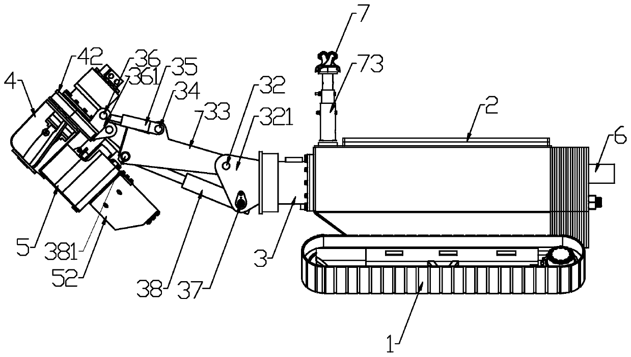
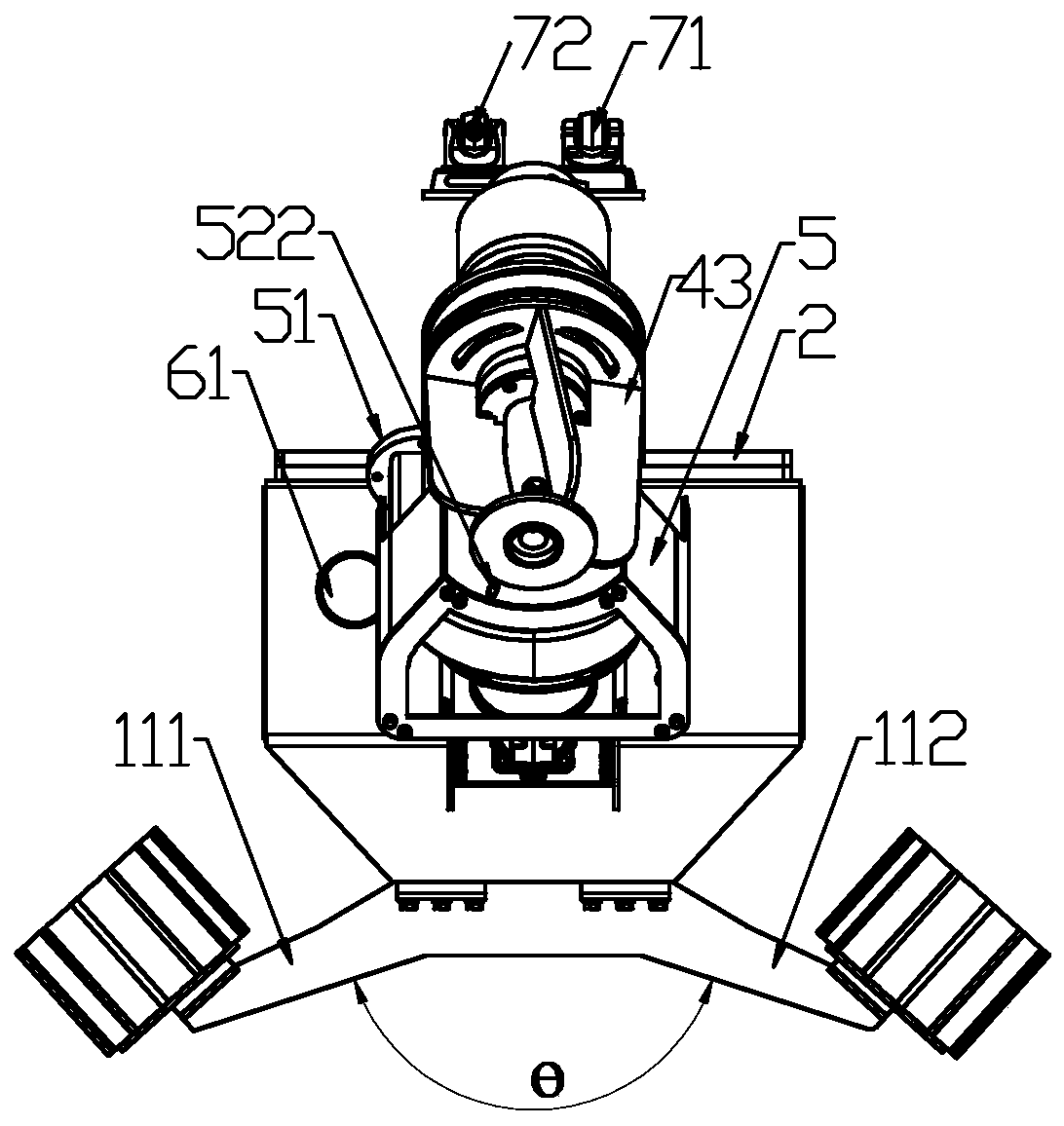
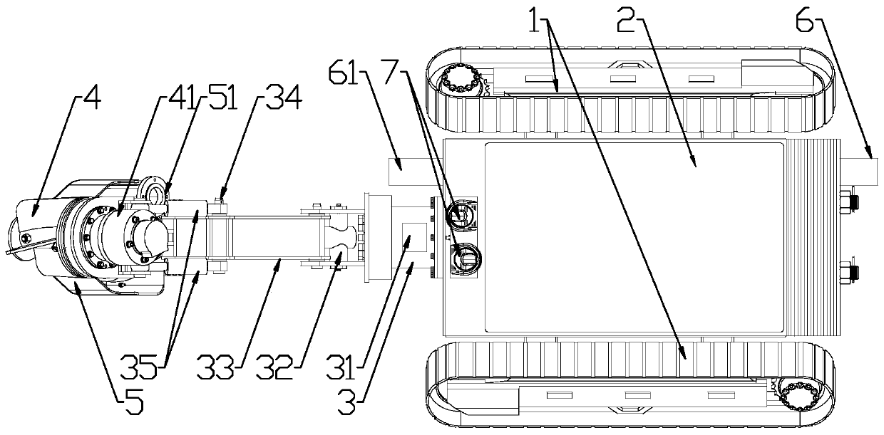
[0020] In this case, the multi-angle pipe dredging device, combined with figure 1 , figure 2 and image 3 , including walking wheel 1 (set according to use needs), main shaft 3, rotating gear 4, mud suction tank 5, mud discharge port 6, camera unit 7 (as a signal input part, which can be set according to use needs) and central control (Fig. not shown in ), the travel wheel 1 is connected with a travel drive (such as a motor, not shown in the figure), the main shaft 3 is located on the travel wheel 1, and is driven by the main shaft (such as a motor, etc., in the figure Not shown) to drive it to rotate (rotate itself, and drive the subsequent rotating gear 4 to rotate accordingly), a multi-stage telescopic arm is arranged between the main shaft 3 and the rotating gear 4, and each telescopic arm is driven by a telescopic arm (such as a cylinder, Hydraulic cylinders and other forms, not shown in the figure), are driven separately. The walking driver, main shaft driver, telesco...


PUM


Abstract

The invention provides a multi-angle in-pipe dredging device, and belongs to the technical field of mobile devices for pipe groove dirt prevention and removal. The multi-angle in-pipe dredging devicecomprises a main rotating shaft, a rotating gear, a sludge sucking groove and a central control, the main rotating shaft is driven to move automatically by a main rotating shaft driver, the rotating gear is driven to move automatically by a rotating gear driver, multi-stage telescopic arms are arranged between the main rotating shaft and the rotating gear, each telescopic arm is driven by a telescopic arm driver, the main rotating shaft driver and the telescopic arm drivers are connected with the central control, and the central control adjusts working states of a travelling driver, the main rotating shaft driver and the telescopic arm drivers so as to meet the needs of dredging in different environments. The multi-angle in-pipe dredging device is applied to the sludge prevention and removal, especially the sludge treatment in a pipe network pool, and has the advantages that accurate dredging is achieved, stable operation is achieved, and the requirements of multi-angle operation are met.

Description

technical field [0001] The application relates to a multi-angle in-pipe dredging device, which belongs to the technical field of moving devices for pipe groove dirt prevention. Background technique [0002] Pipeline structures are widely used in building structures and production activities, and blockage problems will inevitably occur when pipelines transport materials or waste. To solve this problem, it is generally cleaned by manual dredging or pressure difference, but there are different defects: [0003] (1) Although manual dredging can deal with more complex blockages, the sanitary conditions of the staff are worrying, and the visual environment of the pipeline is often not easy to reach directly or does not allow people to directly enter, so it is very difficult to clean and operate. Personnel will also face safety risks caused by hypoxia and small space. In this case, when robots are used to replace manual operations, although the above-mentioned safety risks are avo...

Claims


Application Information

Patent Timeline
Patent Type & Authority Applications(China)
IPC IPC(8): B08B9/049B08B9/051C02F11/00C02F11/12C02F11/14
CPCB08B9/049B08B9/051C02F11/008C02F11/12C02F11/14
Inventor 王兆铨郑文杰吴国君王洁程庆余
Owner 浙江君泰生态环保科技有限公司
Why Eureka
Try Eureka