Cutting-type unmanned under-ice icebreaking submersible vehicle

A cutting-type, submersible technology, applied to icebreakers, underwater ships, underwater operating equipment, etc., can solve the problems of single means, difficult to control the ice-breaking effect, high structural strength requirements of drill bits and submersibles, etc., to improve the ice-breaking ability , expanding the range of navigation, the effect of simple internal structure and control method

Inactive Publication Date: 2019-11-12
HARBIN ENG UNIV
View PDF5 Cites 10 Cited by
  • Summary
  • Abstract
  • Description
  • Claims
  • Application Information

AI Technical Summary

Problems solved by technology

[0002] Common icebreaking methods include icebreaking ship icebreaking method, resonance icebreaking method, bubble icebreaking method, explosive icebreaking method, etc. At present, there are few related researches on icebreaking methods that use unmanned submersibles to break ice from under the ice, and the methods are relatively single
Invention patent CN201711078268.7 mentions an unmanned submersible under ice. This invention uses its own buoyancy and front-end ice-breaking drill bit to break ice by changing its own drainage state. The ice-breaking effect of the submersible is difficult to control in the process of colliding with the ice layer. Moreover, the collision ice-breaking method has higher requirements on the structural strength of the drill bit and the submersible. In addition, this invention is not suitable for continuous ice-breaking
Icebreaking equipment that can use unmanned submersibles to perform continuous icebreaking operations under the ice has not yet been seen

Method used


Image

  • Cutting-type unmanned under-ice icebreaking submersible vehicle
  • Cutting-type unmanned under-ice icebreaking submersible vehicle

Examples


Embodiment Construction

[0015] The present invention will be further described below in conjunction with accompanying drawing:

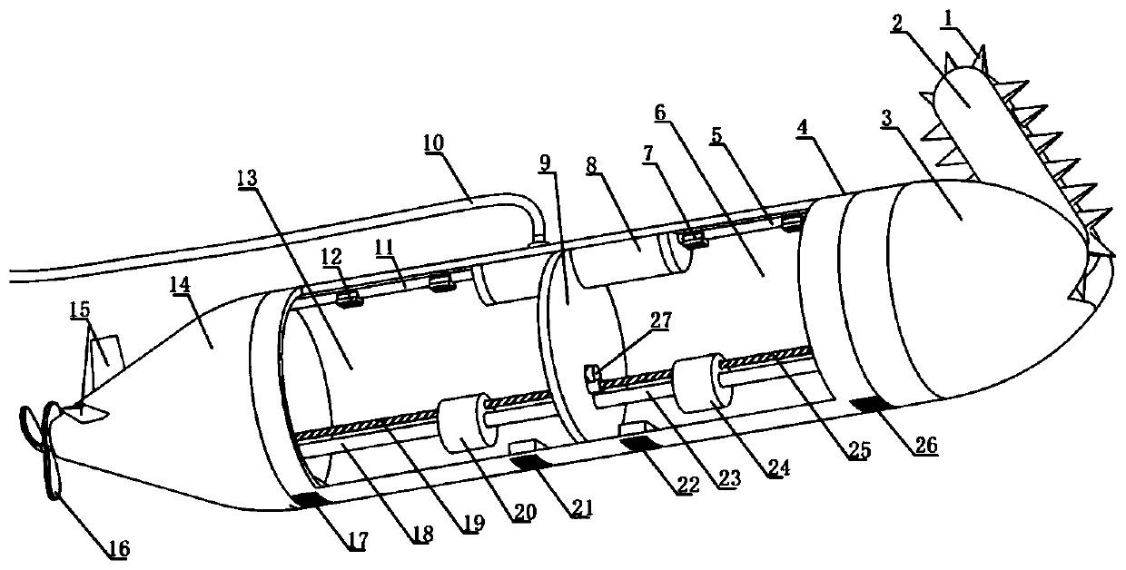
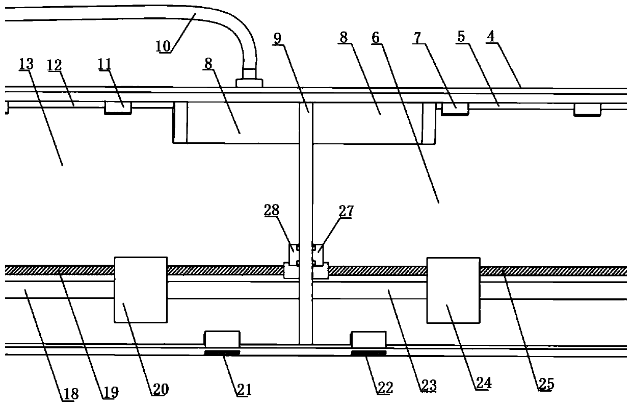
[0016] In the figure: 1. Sawtooth, 2. Ice-breaking saw, 3. Head of submersible, 4. Middle part of submersible, 5. Front air passage, 6. Front ballast water tank, 7. Front air valve, 8. High-pressure gas Cavity, 9. Watertight transverse bulkhead, 10. Umbilical cable, 11. Rear air passage, 12. Rear air valve, 13. Rear ballast water tank, 14. Tail of submersible, 15. Rudder, 16. Propeller , 17. Rear sea valve, 18. Rear slide rail, 19. Rear screw, 20. Rear attitude adjustment counterweight, 21. Rear air valve, 22. Front sea valve, 23. Front slide Rail, 24. the front portion attitude adjustment counterweight, 25. the front portion screw mandrel, 26. the front portion breather valve, 27. the front portion attitude adjustment motor, 28. the rear portion attitude adjustment motor.

[0017] The invention relates to the field of mechanical technology, in particular to a cutting-type...


PUM


Abstract

The invention relates to the technical field of machinery, in particular to a cutting-type unmanned under-ice icebreaking submersible vehicle. The submersible vehicle comprises a submersible vehicle head part, a submersible vehicle middle part and a submersible vehicle tail part; the submersible vehicle head part is composed of an icebreaking saw and sawteeth, the icebreaking saw is located in front of the upper portion of the submersible vehicle head part, and the side edge is defined by the sawteeth; the submersible vehicle middle part is composed of a watertight athwartship bulkhead, a front ballast water tank, a rear ballast water tank, a high pressure air cavity and an air channel, the watertight athwartship bulkhead is located in the submersible vehicle middle part, a cabin of the submersible vehicle middle part is divided into the front ballast water tank and the rear ballast water tank, and the high pressure air cavity and the air channel are located at the top of the submersible vehicle; the submersible vehicle tail part is composed of a propeller and a rudder, and the propeller is in a trifoliate shape and is located behind the submersible vehicle tail part. According tothe embodiment, the icebreaking posture of the submersible vehicle during floating cutting and icebreaking is flexibly controlled, the ice surface can be broken, any shape can be continuously cut on the ice surface, the strength of the overall ice surface is lowered, and the range of damaging the ice surface is flexibly controlled.

Description

technical field [0001] The invention relates to the field of mechanical technology, in particular to a cutting-type unmanned submerged ice-breaking submersible. Background technique [0002] Common icebreaking methods include icebreaking ship icebreaking method, resonance icebreaking method, bubble icebreaking method, explosive icebreaking method, etc. At present, there are few related researches on icebreaking methods that use unmanned submersibles to break ice from under the ice, and the means are relatively single. Invention patent CN201711078268.7 mentions an unmanned submersible under ice. This invention uses its own buoyancy and front-end ice-breaking drill bit to break ice by changing its own drainage state. The ice-breaking effect of the submersible is difficult to control in the process of colliding with the ice layer. And the collision ice-breaking method has higher requirements on the structural strength of the drill bit and the submersible. In addition, this inve...

Claims


Application Information

Patent Timeline
Patent Type & Authority Applications(China)
IPC IPC(8): B63B35/12B63C11/52B63G8/22
CPCB63B35/12B63C11/52B63G8/22
Inventor 周广利徐鹏张栋梁陈自旺郭春雨刘洋李元弟杨波
Owner HARBIN ENG UNIV
Why Eureka
Try Eureka