A multifunctional copper belt machine

A multi-functional, copper tape technology, used in forming tools, safety equipment, metal processing equipment, etc., can solve the problems of not grasping the wire, squeezing to one side, squeezing to one side, and generating burrs, so as to improve the alignment accuracy. , Effective treatment, the effect of improving the outflow rate

Active Publication Date: 2021-09-07
安徽金池新材料有限公司
View PDF6 Cites 0 Cited by
  • Summary
  • Abstract
  • Description
  • Claims
  • Application Information

AI Technical Summary

Problems solved by technology

[0002] Copper strip machine refers to a machine that presses copper sheets to connect wires. It replaces the traditional soldering method. It does not have the disadvantages of cold welding, empty welding and air pollution. Finished quickly and without waste, saving cost. Copper strip terminals are processed with special texture, strong tensile strength after riveting, and stable quality. There are upper mold and lower mold inside the mold base of the copper strip machine. If the molds are not aligned before starting to work, it is easy to cause extrusion to one side, and burrs will be generated when they are extrusion to one side. into the wire, and cause the knife to be clamped

Method used


Image

  • A multifunctional copper belt machine
  • A multifunctional copper belt machine
  • A multifunctional copper belt machine

Examples


Embodiment 1

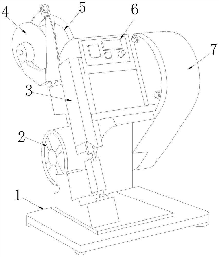
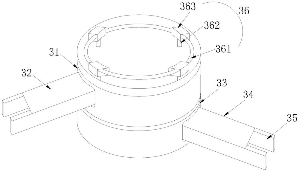
[0027] Such as Figure 1-Figure 3 As shown, the present invention provides a kind of multi-functional copper tape machine, and its structure comprises base 1, traction wheel 2, mold holder 3, feeding wheel 4, line reel 5, control panel 6, main control box 7, and described main control The box 7 is installed on the side of the mold base 3, the mold base 3 is fixed on the base 1, the outer surface of the mold base 3 is provided with a control panel 6, and the control panel 6 is electrically connected to the main control box 7 , the back side of the mold base 3 is mechanically connected with a feeding wheel 4 and a wire management disc 5, and a copper belt is connected between the wire management disc 5 and the feeding wheel 4, and the mold base 3 includes an upper mold 31, an upper mold Shaft 32, lower die 33, lower die shaft 34, cutter loading port 35, mold seat aligner 36, alignment member 37, described upper die 31 and lower die 33 are arranged up and down, and described uppe...

Embodiment 2

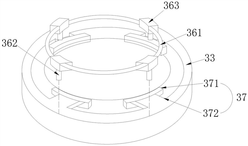
[0029] Such as Figure 4-Figure 5 As shown, the alignment shaft 362 is composed of a vertical shaft 62a, a plug 62b, an input port 62c, a protective cover 62d, an output port 62e, a driver 62f, an inner collection cover 62g, and a balance seat 62h. Both sides of the vertical shaft 62a A top 62b is provided, and the inside of the protective cover 62d is provided with an inner collection cover 62g, a balance seat 62h, and an output port 62e, and the output port 62e is fixed on the balance seat 62h, and the vertical shaft 62a is matched with the calibration groove 372, The driver 62f controls the opening and closing of the output port 62e, and the tip of the plug 62b is provided with an input port 62c, which is matched with the protective cover 62d, and the output port 62e is provided with a port communicating with the inner collection cover 62g. port, the output port 62e is externally connected to the pipeline, the plug 62b is made of rubber, and contacts both sides of the surfa...


PUM


Abstract

The invention discloses a multi-functional copper strip machine, the structure of which comprises a base, a traction wheel, a mold base, a feeding wheel, a wire management disc, a control panel, and a main control box. The main control box is installed on the side of the mold base, and the mold base Fixed on the base, the outer surface of the mold base is provided with a control panel, the control panel is electrically connected to the main control box, and the back of the mold base is mechanically connected to the feeding wheel and the cable management disc, and the transmission between the cable management disc and the feeding wheel is coordinated. There are copper strips, and the mold base includes an upper mold, an upper mold shaft, a lower mold, a lower mold shaft, a cutter loading port, a mold base aligner, and an alignment member. The mold base is used for alignment between the upper mold and the lower mold of the present invention. Only when the alignment shaft is completely embedded in the calibration groove, the upper and lower molds are completely aligned to avoid the situation of being squeezed to one side, and effectively prevent the burr at the cut-off from not being able to catch the line and clamping The knife problem.

Description

technical field [0001] The invention relates to the field of copper strips, in particular to a multifunctional copper strip machine. Background technique [0002] Copper strip machine refers to a machine that presses copper sheets to connect wires. It replaces the traditional soldering method. It does not have the disadvantages of cold welding, empty welding and air pollution. Finished quickly and without waste, saving cost. Copper strip terminals are processed with special texture, strong tensile strength after riveting, and stable quality. There are upper mold and lower mold inside the mold base of the copper strip machine. If the molds are not aligned before starting to work, it is easy to cause extrusion to one side, and burrs will be generated when they are extrusion to one side. Into the line, and lead to knife clamping. Contents of the invention [0003] In view of the above problems, the present invention provides a multifunctional copper strip machine. [0004]...

Claims


Application Information

Patent Timeline
Patent Type & Authority Patents(China)
IPC IPC(8): B21D37/12B21D37/18B21D55/00B21D39/00
CPCB21D37/12B21D37/18B21D39/00B21D55/00
Inventor 刘卫
Owner 安徽金池新材料有限公司
Why Eureka
Try Eureka