High-pressure rubber hose manufacturing and winding processing technology

A technology of high-pressure rubber hose and processing technology, which is applied in the field of high-pressure rubber hose manufacturing and winding processing technology, which can solve the problems of steel wire not being tightly wound, low work efficiency, and fast wire-releasing speed, so as to increase the number of layers of single winding and improve work efficiency. Efficiency, the effect of extending the traction path

Active Publication Date: 2020-07-10
山东德嘉液压制品有限公司
View PDF7 Cites 3 Cited by
  • Summary
  • Abstract
  • Description
  • Claims
  • Application Information

AI Technical Summary

Problems solved by technology

[0004] In order to solve the above problems, the present invention provides a high-pressure rubber hose manufacturing and winding process, which can solve the problem that the steel wire is usually wound on the reel, and the steel wire will be pulled out when winding, thereby driving the reel to rotate. It may be due to the high rotation speed that the pay-off speed is faster than the winding speed, resulting in a loose state of the steel wire during transportation, so that the steel wire cannot be tightly wound on the outer wall of the inner rubber hose, and the overall compactness is reduced. The steel wire wound on the inner rubber hose is usually It is multi-layer winding. The existing winding method is usually single-layer winding, and the effect of multi-layer winding can only be achieved by winding multiple cycles, and the work efficiency is low.

Method used


Image

  • High-pressure rubber hose manufacturing and winding processing technology
  • High-pressure rubber hose manufacturing and winding processing technology
  • High-pressure rubber hose manufacturing and winding processing technology

Examples


Embodiment Construction

[0036] In order to make the technical means, creative features, goals and effects achieved by the present invention easy to understand, the present invention will be further described below in conjunction with specific illustrations. It should be noted that, in the case of no conflict, the embodiments in the present application and the features in the embodiments can be combined with each other.

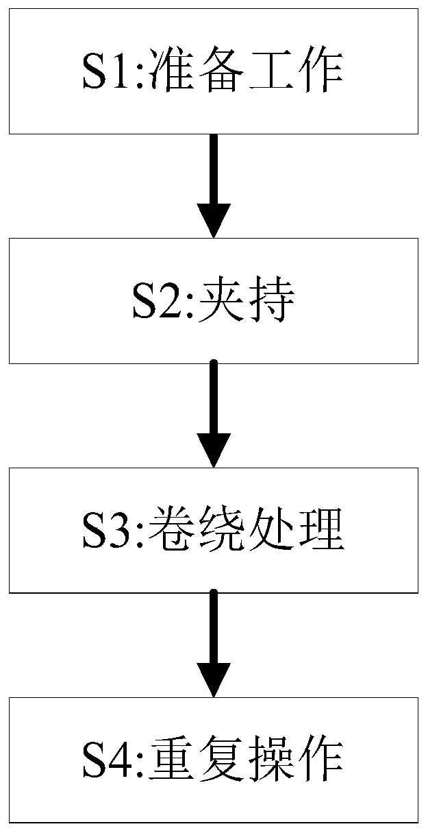
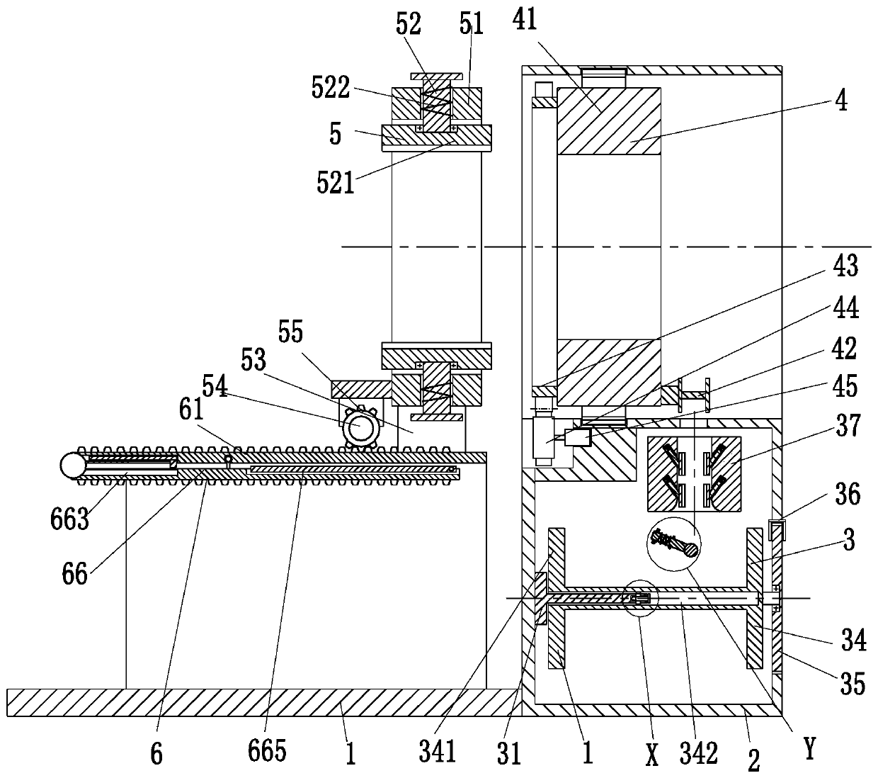
[0037] Such as Figure 1 to Figure 9 As shown, a high-pressure rubber hose manufacturing and winding process uses a steel wire winding equipment. The steel wire winding equipment includes a bottom plate 1, a bottom frame 2, an anti-loosening device 3, a winding drum group 4, and a gap traction device 5 and the folding connecting plate 6, using the above-mentioned steel wire winding equipment to manufacture and wind the high-pressure rubber hose is as follows:

[0038]S1. Preparatory work: pass the free end of the steel wire wound on the reel group 34 through the multi-stage anti-loo...


PUM


Abstract

The invention provides a high-pressure rubber hose manufacturing and winding processing technology. The high-pressure rubber hose manufacturing and winding processing technology is completed through cooperation among a bottom plate, a bottom frame, an anti-loosening device, a winding drum set, a gap traction device and a folding type connecting plate. The high-pressure rubber hose manufacturing and winding processing technology can solve the problems that the overall compactness is reduced due to the fact that a steel wire cannot be tightly wound around the outer wall of an inner rubber pipe due to a loose state of the steel wire in the conveying process caused by the fact that the wire releasing speed is higher than the winding speed due to the high rotating speed in the rotating processof a winding drum due to the fact that the winding drum is driven to rotate by the pulled out steel wire during winding due to the fact that the steel wire is usually wound around the winding drum, and the working efficiency is low due to the fact that the multi-layer winding effect can be achieved through multiple times of circular winding due to the fact that the steel wire wound around the inner rubber pipe is usually wound in a multi-layer mode but an existing winding method usually adopts a single-layer winding mode.

Description

technical field [0001] The invention relates to the field of high-pressure rubber hose production, in particular to a high-pressure rubber hose manufacturing and winding process. Background technique [0002] High-pressure rubber hose has excellent oil resistance, heat resistance, aging resistance, high pressure bearing, superior pulse performance, excellent bending resistance and fatigue resistance. Therefore, high-pressure rubber hose is widely used in petrochemical, coal, electric power, transportation, and medical treatment. In various fields such as equipment, machinery manufacturing, mining, ships, automobiles, etc., during the production process of high-pressure rubber hoses, steel wires need to be wound on the outer wall of the inner rubber hose, and the steel wires play a role in strengthening the skeleton. some problems: [0003] 1. The steel wire is usually wound on the reel. When winding, the steel wire will be pulled out to drive the reel to rotate. During the ...

Claims


Application Information

Patent Timeline
Patent Type & Authority Applications(China)
IPC IPC(8): B21F17/00
CPCB21F17/00
Inventor 宛群赵书跃
Owner 山东德嘉液压制品有限公司
Why Eureka
Try Eureka