
Multi-phase permanent magnet synchronous motor winding design method and motor

A technology of permanent magnet synchronous motor and design method, which is applied to synchronous motors, windings, motors, etc. Problems such as high power density can achieve the effect of maximizing the reluctance torque component, eliminating high-amplitude low-order harmonics, and reducing amplitude harmonic components

Pending Publication Date: 2022-08-09
SHANDONG UNIV
View PDF0 Cites 0 Cited by
  • Summary
  • Abstract
  • Description
  • Claims
  • Application Information

AI Technical Summary

Problems solved by technology

[0003] Compared with the traditional integer slot permanent magnet motor, the fractional slot permanent magnet motor has high torque density, high power density, small volume, large output power, and high efficiency. At the same time, most of the existing winding structures use distributed windings, and the coils The winding is more complex, the end length is long, the copper consumption is large, the efficiency is low, and it is not easy to realize the modular structure, the phases are easy to couple, and the fault tolerance performance is poor. Therefore, the use of concentrated windings is becoming more and more widespread. It has been widely used in power generation, ship propulsion, aerospace and other fields
[0004] However, due to the current distribution in the fractional slot permanent magnet motor windings, the armature magnetomotive force contains high-amplitude low-order harmonics. These harmonics operate asynchronously in the iron core and permanent magnets, and the iron core and permanent magnets generate large eddy currents. losses, resulting in reduced operating efficiency of permanent magnet motors
In addition, it is difficult to release heat from the permanent magnet motor rotor, causing the motor to overheat, and may even cause the permanent magnet to overheat and cause irreversible demagnetization, forming a safety hazard during the use of the motor
On the other hand, these harmonics interact spatially, causing undesirable noise and vibration on the permanent magnet motor, which affects the service life of the motor

Method used


Image

  • Multi-phase permanent magnet synchronous motor winding design method and motor
  • Multi-phase permanent magnet synchronous motor winding design method and motor
  • Multi-phase permanent magnet synchronous motor winding design method and motor

Examples


Embodiment 1

[0038] This embodiment provides a method for designing windings of a multi-phase permanent magnet synchronous motor with high fault tolerance.

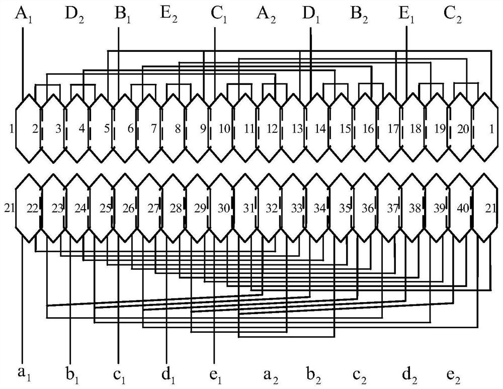
[0039] A high fault-tolerant multi-phase permanent magnet synchronous motor winding design method, which is applied to the winding winding method on the inner stator or the outer stator of the motor, the winding winding method adopts the fractional slot phase group concentrated winding method, and the fractional slot phase group winding method is adopted. The concentrated winding method of the phase group includes the inner and outer stators connected in the same way or in different ways;

[0040] The same connection method is that both the inner and outer stators adopt the star-star connection method, the different connection methods are that the outer stator adopts the star-star connection method, and the inner stator adopts the star-pentagon star connection method.

[0041] Specifically, a polyphase permanent magnet synchronous mot...

Embodiment 2

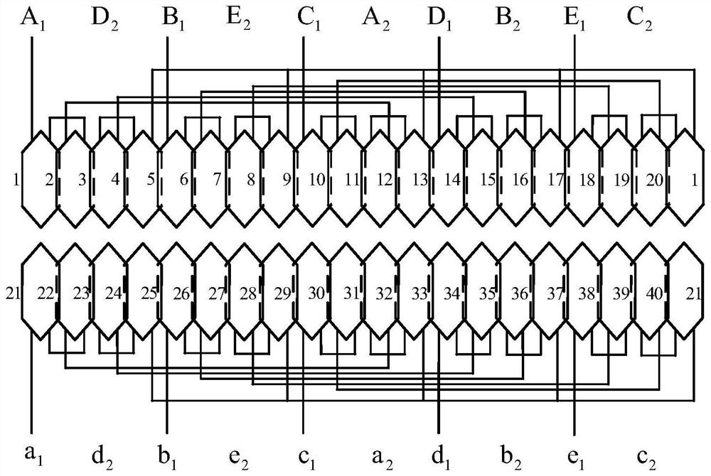
[0056] like figure 2 As shown, the outer stator winding of the second winding method is as follows:

[0057] A 1 : A 1 -1, 1-2, 2-3, 3-2, 2-12, 12-11, 11-12, 12-13, 13-A 2 ;

[0058] B 1 :B 1 -5, 5-6, 6-7, 7-6, 6-16, 16-15, 15-16, 16-17, 17-B 2 ;

[0059] C 1 :C 1 -9, 9-10, 10-11, 11-10, 10-20, 20-19, 19-20, 20-1, 1-C 2 ;

[0060] D 1 :D 1 -13, 13-14, 14-15, 15-14, 14-4, 4-3, 3-4, 4-5, 5-D 2 ;

[0061] E 1 :E 1 -17, 17-18, 18-19, 19-18, 18-8, 8-7, 7-8, 8-9, 9-E 2 .

[0062] Wherein, the winding of the inner stator main winding of the second winding method is as follows:

[0063] a 1 : a 1 -21, 21-22, 22-32, 32-31, 31-a 2 ;

[0064] b 1 :b 1 -23, 23-24, 24-34, 34-33, 33-b 2 ;

[0065] c 1 :c 1 -25, 25-26, 26-36, 36-35, 35-c 2 ;

[0066] d 1 :d 1 -27, 27-28, 28-38, 38-37, 37-d 2 ;

[0067] e 1 : e 1 -29, 29-30, 30-40, 40-39, 39-e 2 .

[0068] The winding method of the secondary winding is as follows:

[0069] a 1 -22, 22-23, 23-a 2 , a ...

Embodiment 3

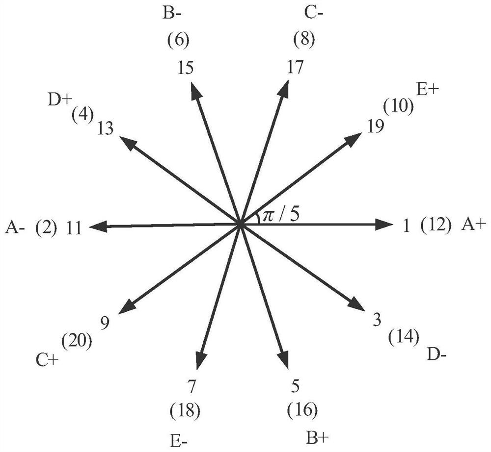
[0072] Combined with the first embodiment, in order to achieve the high performance of the permanent magnet synchronous motor, the stator winding is in a concentrated winding mode, the purpose is to improve the winding coefficient and reduce the end winding, and improve the efficiency of the motor, and each phase winding adopts a modular design. The two sets of stator windings of the five-phase motor can be independently controlled, and the dual five-phase control strategy can further improve the fault tolerance of the motor. The design principle of this embodiment is as follows:

[0073] The windings of the five-phase permanent magnet synchronous motor are connected according to Figure 4(a) and Figure 4(b).

[0074] First determine the pole-slot fit, the formula is based on:

[0075]

[0076] Among them, Z is the number of stator slots, GCD(Z, 2p) is the greatest common divisor of the number of stator slots and the number of poles, and C is any positive integer. The pole...


PUM


Abstract

The invention belongs to the field of multiphase permanent magnet synchronous motor design and manufacturing, and provides a multiphase permanent magnet synchronous motor winding design method and a motor. The winding design method is applied to a winding winding mode on an inner stator or an outer stator of a motor, the winding winding mode adopts a fractional-slot phase group concentrated winding mode, and the fractional-slot phase group concentrated winding mode comprises the mode that the inner stator and the outer stator are connected in the same mode or different modes. Wherein the same connection mode is that the inner stator and the outer stator both adopt a star-star connection method, and the different connection modes are that the outer stator adopts the star-star connection method and the inner stator adopts a star-five-pointed star connection method.

Description

technical field [0001] The invention belongs to the field of design and manufacture of a multiphase permanent magnet synchronous motor, and particularly relates to a winding design method and a motor of a multiphase permanent magnet synchronous motor. Background technique [0002] The statements in this section merely provide background information related to the present invention and do not necessarily constitute prior art. [0003] Compared with traditional integer-slot permanent magnet motors, fractional-slot permanent magnet motors have high torque density, high power density, small size, high output power, and high efficiency. The winding is more complicated, the length of the end is long, the copper consumption is large, and the efficiency is low. At the same time, it is not easy to achieve a modular structure, and the phases are easily coupled, and the fault tolerance performance is poor. Therefore, the use of concentrated windings is becoming more and more extensive....

Claims


Application Information

Patent Timeline
Patent Type & Authority Applications(China)
IPC IPC(8): H02K3/28H02K3/52H02K3/48H02K3/12H02K15/085H02K16/00H02K16/04H02K21/12
CPCH02K3/28H02K3/522H02K3/48H02K3/12H02K15/085H02K16/00H02K16/04H02K21/12H02K2213/03Y02T10/64
Inventor 赵文良丁海波刁成武王秀和
Owner SHANDONG UNIV
Learn More