
Combined permanent magnet brushless motor stator and manufacturing method thereof

A technique of permanent magnet brushless motor and manufacturing method, which is applied in the manufacture of motor generators, stator/rotor bodies, magnetic circuits, etc., and can solve the problem of low material utilization rate, inability to use three-phase permanent magnet synchronous motors, and material utilization rate. Not high problems, to achieve the effect of improving utilization rate, high slot full rate, and improving utilization rate

Pending Publication Date: 2019-07-12
杨世国
View PDF5 Cites 7 Cited by
  • Summary
  • Abstract
  • Description
  • Claims
  • Application Information

AI Technical Summary

Problems solved by technology

The disadvantages of this process design are: First, the utilization rate of materials is very low, about 35%. If high-performance materials are used, it will be a pity
The patent CN101043154A "Stator assembly and manufacturing method for asynchronous motors" of Guangdong Welling Motor Manufacturing Co., Ltd. is a stator scheme for unidirectional asynchronous motors proposed for small household appliances, and it cannot be used for three-phase permanent magnet synchronous motors with distributed windings. , and the teeth and yoke are punched in one piece, the material utilization rate is not high

Method used


Image

  • Combined permanent magnet brushless motor stator and manufacturing method thereof
  • Combined permanent magnet brushless motor stator and manufacturing method thereof
  • Combined permanent magnet brushless motor stator and manufacturing method thereof

Examples


Embodiment Construction

[0028] The following takes a 3-phase 24-slot combined permanent magnet brushless motor stator as an example to illustrate the specific design and manufacturing method. This 3-phase 24-slot stator can be used to make fractional slots with a permanent magnet rotor with a pole pair number 2p=10-20. Permanent magnet brushless motors are also suitable for distributed winding motors with integral slots made of permanent magnet rotors with 2p=2-8, as follows.

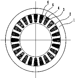
[0029] Example 1, 2p=16 fractional slot motor, the number of phases m=3, the number of slots Q=24, then the number of slots per pole and phase q=0.5. Rotor diameter D1=99, stack thickness L=60, stator inner diameter 100, outer diameter 160, air gap δ=0.5, tooth width 8, radial tooth height 22, radial yoke width 8.

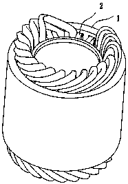
[0030] Production of tooth core 2 ( Figure 4 ). First, the silicon steel strip is punched out into a long strip with teeth and grooves according to the design requirements; then the toothed strip is spirally sta...


PUM


Abstract

The invention provides a combined permanent magnet brushless motor stator and a manufacturing method thereof. A stator core is formed by a tooth part iron core formed by winding and a yoke part iron core, the tooth part iron core is located inside, the yoke part iron core is located outside, an inner circular surface of the tooth part iron core has no notch, a winding is placed into a groove froman outer circular surface or is wounded tooth by tooth, a tooth part winding is sleeved in the yoke part iron core to form a stator assembly after being manufactured, the invention is suitable for a fractional slot winding is also suitable for a distributed winding, the iron core has no slot and almost has no cogging torque, the motor running performance is good, the material utilization rate is high, the design is optimized and flexible, the motor efficiency and specific power are easy to improve, and the automatic production is easy to achieve.

Description

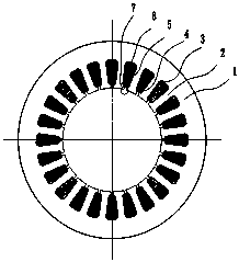
technical field [0001] The invention belongs to the field of motors, in particular to a design and manufacturing method of a motor stator. Background technique [0002] As a kind of power machinery, motor has a history of more than one hundred years, and various motors are widely used in various aspects of social production and life. Especially for new energy vehicles, new and higher requirements are put forward for the drive control performance, manufacturing and use cost, and volume weight of the motor. For the motor in which the stator is configured outside the rotor, the prior art stator ( figure 1 ) are usually stacked with inwardly grooved annular silicon steel punches. The disadvantages of this process design are: First, the material utilization rate is very low, about 35%, and it is even more pity if high-performance materials are used. Someone has proposed the design of various combined iron cores for this reason, such as domestic disclosed CN108808917A. Japan, ...

Claims


Application Information

Patent Timeline
Patent Type & Authority Applications(China)
IPC IPC(8): H02K1/14H02K1/18H02K15/085H02K15/02
CPCH02K1/146H02K1/18H02K15/085H02K15/022H02K15/026
Inventor 杨世国
Owner 杨世国
Learn More