Crankshaft pendulum assembly having kidney-shaped track

a technology of pendulum and crankshaft, which is applied in the direction of rotating vibration suppression, vibration suppression adjustment, shaft and bearing, etc., can solve the problems of high crankshaft torsional vibration, high engine block vibration, and ultimately transmission of torsional vibration through the engine mount, so as to reduce nvh

Active Publication Date: 2016-01-14
FORD GLOBAL TECH LLC
View PDF2 Cites 3 Cited by
  • Summary
  • Abstract
  • Description
  • Claims
  • Application Information

AI Technical Summary

Benefits of technology

[0010]The disclosed inventive concept overcomes the challenges faced by known pendulum crankshaft arrangements for internal combustion engines by providing a maximum “drop” gap of less than 0.5 mm between the rolling pin and the walls of the carrier and pendulum tracks. When the engine is turned off and the rotational movement of the crankshaft ceases along with the centrifugal force acting on the pendulum, the small drop experienced by the pendulum when stopped in its “up” position results in reduced NVH.

Problems solved by technology

An undesirable consequence of engines with a small number of cylinders is high crankshaft torsional vibration and high engine block vibration caused by forces, such as first and second engine order forces, that are not cancelled.
Such torsional vibrations are ultimately transmitted through the engine mounts and to the vehicle structure.
Engineers managed these vibrations to one extent or another through a variety of approaches, many of which increase the cost of construction and reduce fuel economy.
However, when the engine is turned off and rotational movement of the crankshaft stops, centrifugal motion stops as well and the pendulum, no longer held in its fully outward position, may experience a drop caused by gravity if the stopped position of the pendulum is “up” or is generally above the midline of the crankshaft.
If the pendulum is stopped in this position, then it will drop a distance of over 3.0 mm before hitting metal-on-metal, thus increasing undesirable NVH in the engine and, consequently, in the vehicle.
The use of such corrective measures not only adds to manufacturing and material cost, but also creates a risk of clogged oil lines by particles of rubber due to the degradation of the rubber over time.

Method used


Image

  • Crankshaft pendulum assembly having kidney-shaped track
  • Crankshaft pendulum assembly having kidney-shaped track
  • Crankshaft pendulum assembly having kidney-shaped track

Examples


Embodiment Construction

[0022]In the following figures, the same reference numerals will be used to refer to the same components. In the following description, various operating parameters and components are described for different constructed embodiments. These specific parameters and components are included as examples and are not meant to be limiting.

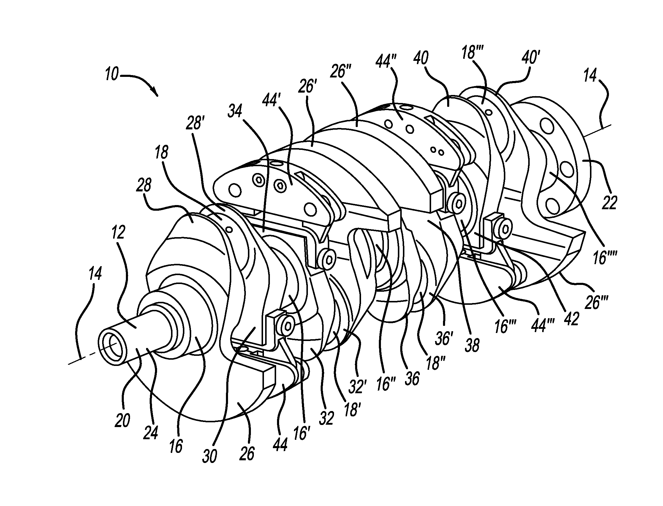
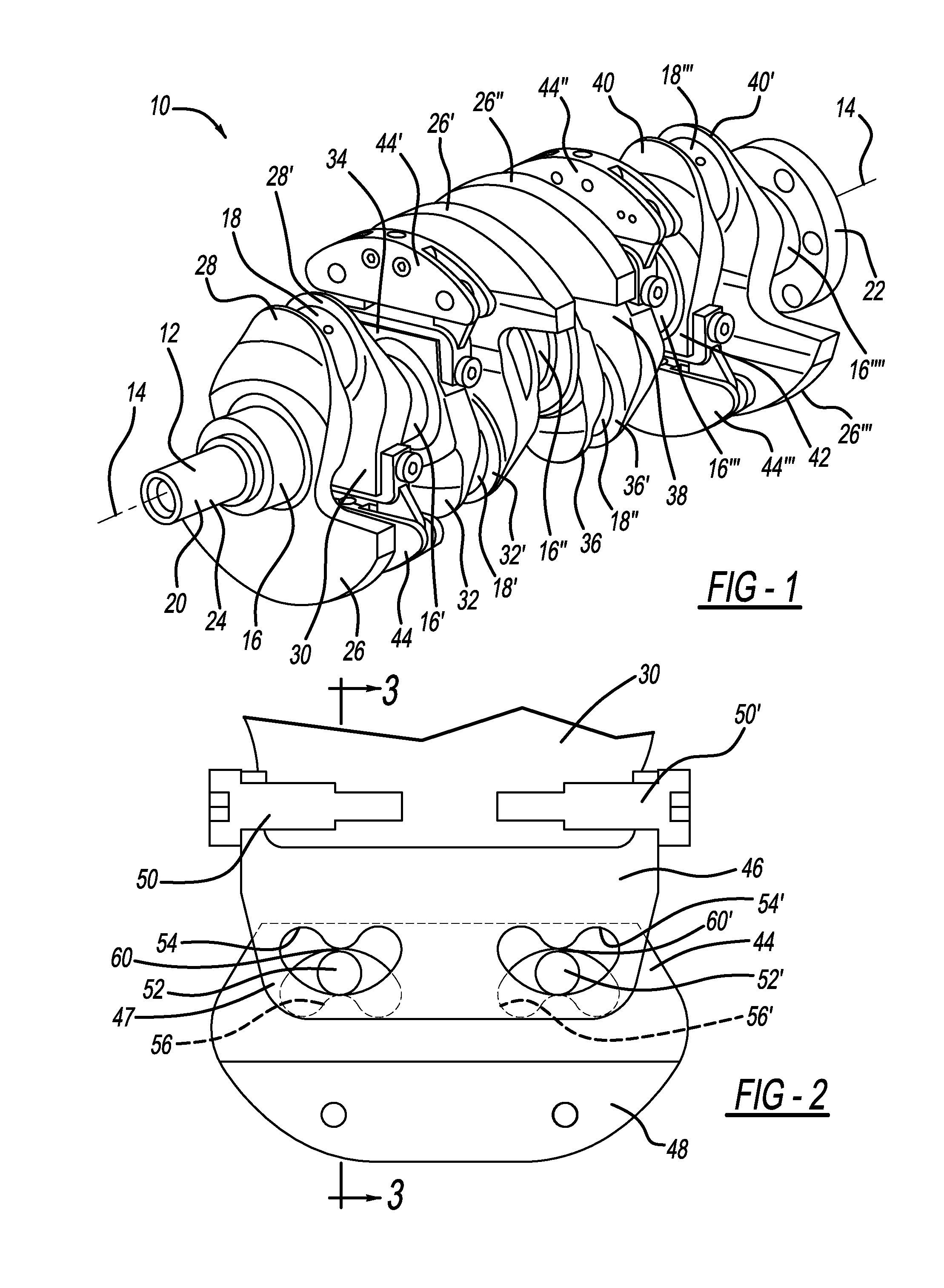
[0023]Referring to FIG. 1, a crankshaft assembly for an internal combustion engine is illustrated. It is to be understood that the overall configuration of the illustrated crankshaft assembly, generally illustrated as 10 in FIGS. 1, is set forth for suggestive purposes only as the overall configuration may be altered from that illustrated.

[0024]The crankshaft assembly 10 includes a crankshaft 12. The crankshaft 12 has a rotational axis 14. Rotation of the crankshaft 12 about its rotational axis 14 is made possible by the provision of main journals 16, 16′, 16″, 16′″ and 16″″. The journals 16, 16′, 16″, 16′″ and 16″″ are integrally formed as part of the cran...


PUM


Abstract

A pendulum crankshaft assembly for an internal combustion engine includes a pendulum carrier, a pendulum and rolling pins. The carrier and the pendulum have kidney-shaped rolling pin tracks. The rolling pin tracks are kidney-shaped and thus are defined by opposed curved side walls and opposed end walls. The pendulum carrier has an ear extending therefrom to which the pendulum is attached. The pendulum comprises a first half and a second half, each half being positioned on the sides of the ear. At any given time in operation, the gap between the rolling pin and the opposed walls of the rolling pin tracks is never greater than 0.5 mm. The pendulum carrier is attached to a cheek of the crankshaft by a pair of opposed fasteners.

Description

TECHNICAL FIELD[0001]The disclosed inventive concept relates generally to pendulum crankshafts for internal combustion engines. More particularly, the disclosed inventive concept relates to kidney-shaped rolling pin tracks formed in the pendulum carrier assembly.BACKGROUND OF THE INVENTION[0002]Internal combustion engines having a relatively small number of cylinders provide automobile makers with an attractive solution to the need for improved fuel economy. In order to compensate for reduction of cubic capacity vehicle manufacturers developed technologies to improve engine power, such as direct fuel injection, turbocharging, and variable timing for inlet and exhaust camshafts. In this way six- and eight-cylinder engines can be scaled down without losing available horsepower.[0003]An undesirable consequence of engines with a small number of cylinders is high crankshaft torsional vibration and high engine block vibration caused by forces, such as first and second engine order forces,...

Claims


Application Information

Patent Timeline
Patent Type & Authority Applications(United States)
IPC IPC(8): F16F15/14
CPCF16F15/145F16C3/20
Inventor BREVICK, JOHN EDWARDWOODSIDE, WAYNE PAULCHOTTINER, JEFFREY ELIOTWILLIAMS, RICK L.HANSON, FRANK
Owner FORD GLOBAL TECH LLC
Why Eureka
Try Eureka