Automatic assembling equipment for gear shaft

An automatic assembly and gear shaft technology, applied in metal processing equipment, assembly machines, manufacturing tools, etc., can solve problems such as low production efficiency and high labor intensity, and achieve the effects of improving production efficiency, wide applicability, and accurate positioning

Pending Publication Date: 2020-07-10
CHONGQING ROBOT
View PDF0 Cites 5 Cited by
  • Summary
  • Abstract
  • Description
  • Claims
  • Application Information

AI Technical Summary

Problems solved by technology

[0003] The purpose of the present invention is to provide an automatic gear shaft assembly equipment to solve the problems of low production efficiency and high labor intensity caused by manual assembly in the prior art

Method used


Image

  • Automatic assembling equipment for gear shaft
  • Automatic assembling equipment for gear shaft
  • Automatic assembling equipment for gear shaft

Examples


Embodiment Construction

[0024] The following is further described in detail by specific embodiments:

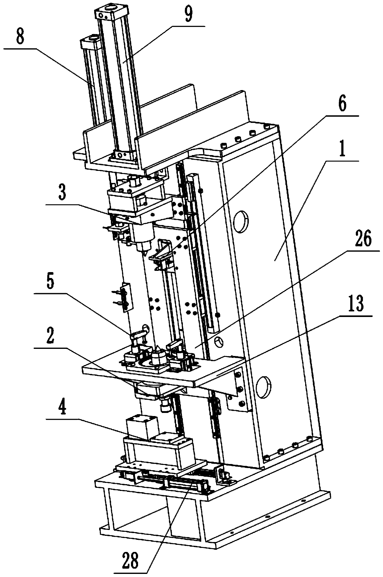
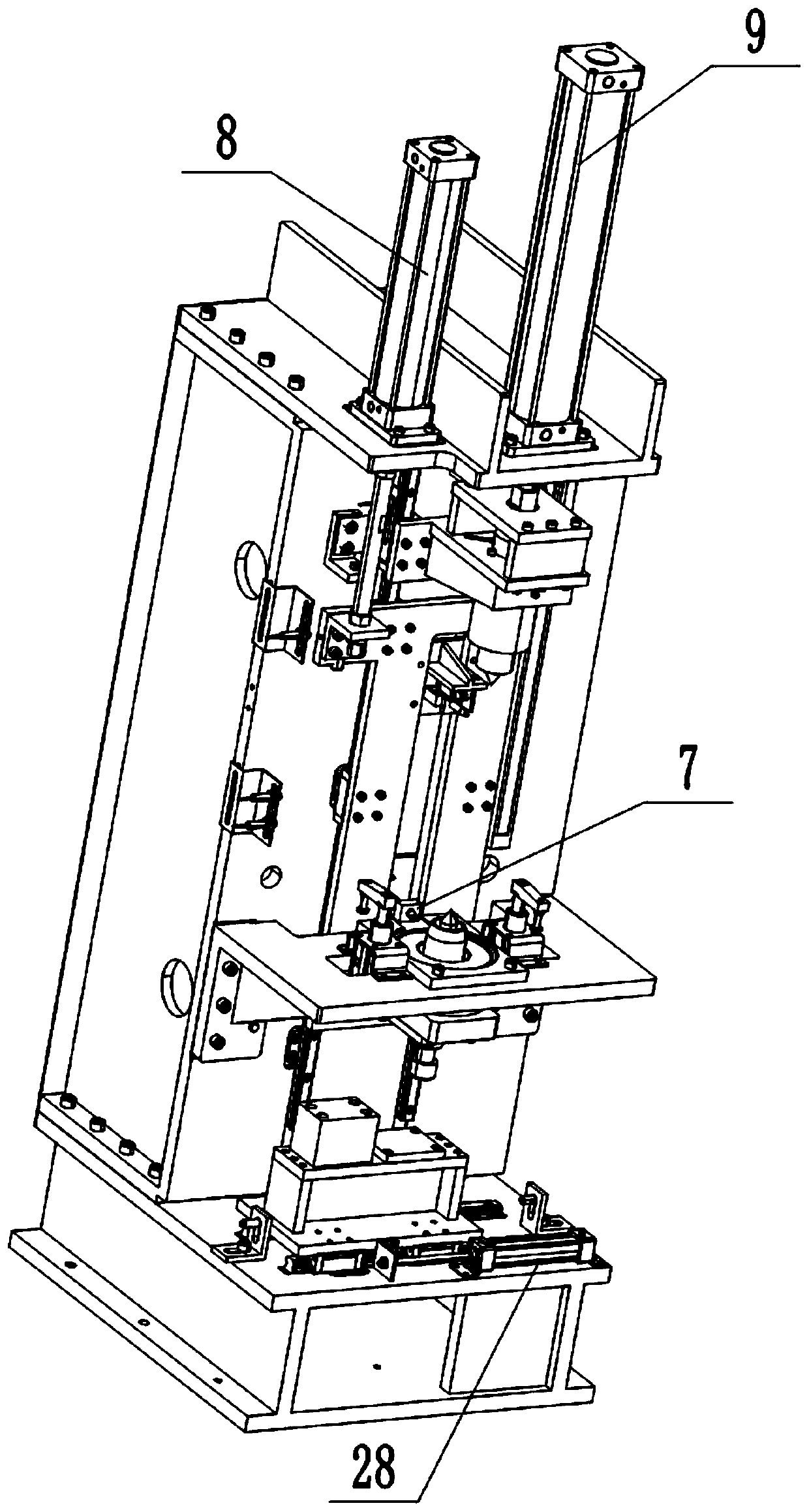
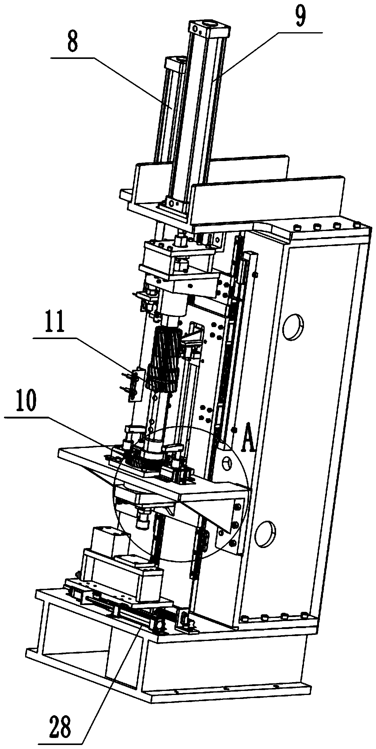
[0025] Reference numerals in the accompanying drawings include: frame 1, positioning unit 2, assembling unit, limiting unit 4, clamping unit 5, shaft-to-tooth portion 6, wheel-to-tooth portion 7, first driving member 8, Two driving parts 9, gear 10, gear shaft 11, limit seat 12, fixing plate 13, limit column 14, positioning seat 15, positioning column 16, first protrusion 17, first groove 18, through hole 19, The assembly seat 20 , the assembly column 21 , the second protrusion 22 , the sixth driving member 23 , the driving rod 24 , the clamping block 25 , the mounting plate 26 , the supporting plate 27 , and the third driving member 28 .

[0026] The technical solutions in the embodiments of the present invention will be clearly and completely described below with reference to the accompanying drawings in the embodiments of the present invention. Obviously, the described embodiments are only a part...


PUM


Abstract

The invention belongs to the technical field of assembling equipment, and particularly discloses an automatic assembling equipment for a gear shaft. The automatic assembling equipment for the gear shaft comprises a controller, a machine frame, and a positioning unit, an assembling unit, a tooth aligning unit and a limiting unit which are arranged on the machine frame; the positioning unit is usedfor supporting and centering a gear; the assembling unit is positioned above the positioning unit; the assembling unit and the positioning unit are used for centering and clamping the gear shaft; thetooth aligning unit is used for aligning teeth of the gear and the gear shaft; and the limiting unit is used for limiting the positioning unit. By using the assembling equipment, the problems of low production efficiency and high labor intensity caused by adopting a manual assembling mode in the prior art can be solved.

Description

technical field [0001] The invention belongs to the technical field of assembling equipment, and particularly relates to an automatic assembling equipment for gear shafts. Background technique [0002] The gear is an indispensable part in the car, and the gear in the car needs to be assembled with the gear shaft. The existing gear installation tool is to place the gear on the tool, cooperate with manual use of a copper hammer to knock, and assemble the heated gear to the camshaft. This method is easy to cause the gear to be biased, and at the same time, the labor intensity is high and the production efficiency is high. Low. SUMMARY OF THE INVENTION [0003] The purpose of the present invention is to provide an automatic gear shaft assembly equipment, so as to solve the problems of low production efficiency and high labor intensity caused by manual assembly in the prior art. [0004] In order to achieve the above purpose, the technical solution of the present invention is...

Claims


Application Information

Patent Timeline
Patent Type & Authority Applications(China)
IPC IPC(8): B23P21/00
CPCB23P21/004
Inventor 章涛张晓兰曾君樊董泓何发高蔺成荣李强
Owner CHONGQING ROBOT
Why Eureka
Try Eureka