
Truss robot grabbing device

The technology of a truss robot and a grabbing device, which is applied in the field of truss robots, can solve the problems of low grabbing ability, poor versatility, and low grabbing efficiency, and achieve the effects of improving automation rate, improving use efficiency, and enhancing versatility

Active Publication Date: 2020-07-10
NINGXIA KOCEL MOLD
View PDF8 Cites 0 Cited by
  • Summary
  • Abstract
  • Description
  • Claims
  • Application Information

AI Technical Summary

Problems solved by technology

The disadvantage of this type of structure is that it cannot grab sand cores with a small thickness or place sand cores with a small gap between the left and right sand cores
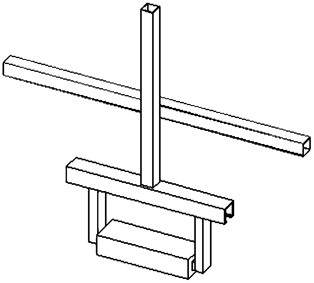
One situation is that when two sand cores are stacked up and down, if the thickness of the upper sand core is close to the thickness of the hanger, then when the truss is grabbed, the lower wall of the truss gripper will touch the lower sand core, causing interference. As a result, the truss cannot grab the sand core; another situation is when the sand core is placed on the left and right (sand core hanger first) if the distance between the two sand core hangers is less than the wall thickness of the truss handle (the wall thickness of the truss handle is generally Between 200mm and 350mm), when the truss gripper descends to grab one of the sand cores, the outer wall of the truss gripper will touch the sand core next to the sand core, that is to say, the truss arm and the other sand core have a collision. Interference caused that the truss gripper could not continue to descend to grab the sand core
Therefore, the current truss can only solve the grabbing of some sand cores, resulting in low grabbing ability, low grabbing efficiency, and poor versatility.

Method used


Image

  • Truss robot grabbing device
  • Truss robot grabbing device
  • Truss robot grabbing device

Examples


Embodiment Construction

[0027] In order to facilitate the understanding of the present invention, the present invention will be more fully described below with reference to the accompanying drawings of the relevant specification. The preferred embodiments of the present invention are given in the accompanying drawings of the specification. However, the present invention can be implemented in many different forms and is not limited to the embodiments described herein. On the contrary, the purpose of providing these embodiments is to make the disclosure of the present invention more thorough and comprehensive.

[0028] Unless otherwise defined, all technical and scientific terms used herein have the same meaning as commonly understood by those skilled in the technical field of the present invention. The terminology used in the specification of the present invention herein is only for the purpose of describing specific embodiments, and is not intended to limit the present invention. The term "and / or" as ...


PUM


Abstract

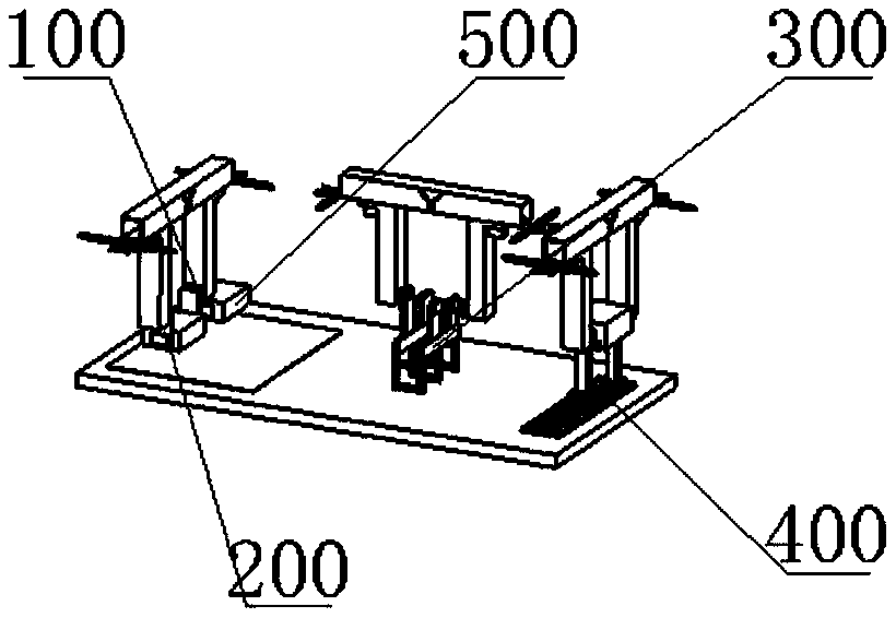
The invention belongs to the technical field of truss robots, and particularly relates to a truss robot grabbing device. The grabbing device comprises a common gripper and a quick-change gripper. Thequick-change gripper comprises a C-shaped quick-change gripper, a sling type quick-change gripper and an opening-closing type quick-change gripper. The common gripper is used for grabbing common sandcores. The quick-change gripper is used for grabbing special sand cores which cannot be grabbed by the common gripper. In order to overcome the defects in the prior art, the truss robot grabbing device is provided. The three quick-change gripper structures can effectively grab the sand cores of various different structures, and the proper quick-change gripper is flexibly adopted according to the structures of the sand cores. Thus, the grabbing device can automatically grab the sand cores of any structure, the problems that an existing truss robot cannot grab thin sand cores and the sand coresare placed in a short distance are solved, the grabbing automation rate is increased, and the universality of a truss is enhanced.

Description

Technical field [0001] The invention relates to the technical field of truss robots, in particular to a truss robot grasping device. Background technique [0002] At present, truss robots usually adopt a gantry frame structure, which includes X-axis, Y-axis, Z-axis, gripper structure, rotating structure, and flipping structure. figure 1 In order to omit the schematic diagram of the truss gripper behind the X axis, the turning structure, the rotating structure, and each part of the movement device, the way the gripper grabs the sand core is described. As shown in the figure, the foundry sand core is usually provided with hanging handles corresponding to the truss robot gripper on two opposite surfaces. The truss gripper moves to the place where the sand core is placed, and the sand core is grasped through the lifting, opening and closing functions. The disadvantage of this type of structure is that it cannot grab a sand core with a small thickness or place a sand core with a small...

Claims


Application Information

Patent Timeline
Patent Type & Authority Applications(China)
IPC IPC(8): B25J15/00
CPCB25J15/00B25J15/0052
Inventor 冯艳艳黄部东孙伟
Owner NINGXIA KOCEL MOLD
Learn More