
High-speed water entry buffer head cap of underwater vehicle

An underwater vehicle and buffer head technology, applied in the directions of underwater ships, underwater operation equipment, ships, etc., can solve the problems of inability to provide electromagnetic protection, limited buffer performance, unreliable installation, etc., and achieve excellent electromagnetic shielding performance and Thermal performance, vibration damping stress amplitude, effect of protecting electrical components

Pending Publication Date: 2020-07-10
NORTHWESTERN POLYTECHNICAL UNIV
View PDF8 Cites 12 Cited by
  • Summary
  • Abstract
  • Description
  • Claims
  • Application Information

AI Technical Summary

Problems solved by technology

However, the above-mentioned patents have disadvantages such as complex structure, unreliable installation, inability to provide electromagnetic protection, and limited cushioning performance, and their applications are limited.

Method used


Image

  • High-speed water entry buffer head cap of underwater vehicle

Examples


Embodiment Construction

[0022] Now in conjunction with embodiment, accompanying drawing, the present invention will be further described:

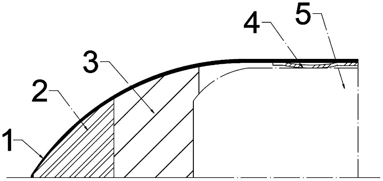
[0023] The buffer head cap designed by the present invention is mainly composed of a casing 1, a metal foam buffer 2, a foam plastic buffer 3, and a joint 4.

[0024] The casing 1 adopts the shape of a small ball head pointed arch, which is a commonly used aerodynamic shape. According to the speed and angle of the aircraft flying in the air, the maximum aerodynamic load and the minimum water impact load of the aircraft are simulated to determine the strength design range of the outer shell of the cushioning headgear.

[0025] The length of each part of the composite structure buffer is determined according to the hull strength of the aircraft 5 and the dynamic compression mechanical properties of the buffer material.

[0026] The buffer is a revolving body, followed by a metal foam buffer 2 and a foam plastic buffer 3, and the two are close to each other without...


PUM


Abstract

The invention relates to a high-speed water entry buffer head cap of an underwater vehicle. The high-speed water entry buffer head cap comprises an outer cover shell, a combined buffer piece and a combining piece. The outer cover shell is installed outside the whole buffering head cap, so that the aircraft has a good pneumatic head shape, the stability of the whole structure of the buffering headcap is guaranteed in the air flying stage; the buffering head cap can be integrally broken and disintegrated when entering water, and the movement performance of the aircraft in water is not affected.The combined buffer piece can isolate the impact when entering water to reduce and limit the water entering impact load acting on the aircraft. The combined buffer piece is a revolving body and bonded at the front end inside the cover shell, a groove is formed in the rear end of the buffer and completely wraps the head of the aircraft, and the combined surface of the combined buffer piece and thebuffer serves as a supporting surface and a supporting point for combining the aircraft and the head cap. A connecting piece adopts a spring clamp device to guarantee firm and reliable connection between the aircraft and the buffer head cap, and resistance to disengagement loads of the aircraft in various mechanical environments such as impact, vibration and external loads in the carrying and running process is realized.

Description

technical field [0001] The invention belongs to the design field of a water-entry buffer device for an underwater vehicle, and relates to a high-speed water-entry buffer cap for an underwater vehicle. Background technique [0002] my country is a country with both land and sea. Its territorial waters cover an area of ​​more than 4.7 million square kilometers and its coastline is as long as 18,000 kilometers. It has abundant marine resources. In order to safeguard national maritime sovereignty and efficiently develop marine resources, it is necessary to develop underwater vehicles of. Underwater vehicles can be launched by air. The advantage of air delivery is that the aircraft can carry the aircraft to a specific work area for delivery, which is conducive to the faster work of the aircraft. Research on air delivery of underwater vehicles has attracted the attention of various countries. [0003] During the impact process of the underwater vehicle being dropped into the water...

Claims


Application Information

Patent Timeline
Patent Type & Authority Applications(China)
IPC IPC(8): B63B43/18B63G8/00
CPCB63B43/18B63G8/001
Inventor 施瑶高兴甫潘光宋保维黄桥高
Owner NORTHWESTERN POLYTECHNICAL UNIV
Learn More