
Mounting structure and mounting method for precisely burying cast-in-situ bored pile protection barrel

A technology for drilling cast-in-place piles and installation structures, which is used in infrastructure engineering, sheet pile walls, buildings, etc., can solve the problems of inability to monitor and the positioning accuracy of the casing is not high, and achieves increased investment, improved work efficiency and pile foundations. The effect of positioning accuracy and good adaptability

Inactive Publication Date: 2020-07-10
CHINA FIRST METALLURGICAL GROUP
View PDF13 Cites 2 Cited by
  • Summary
  • Abstract
  • Description
  • Claims
  • Application Information

AI Technical Summary

Problems solved by technology

[0004] The purpose of the present invention is to provide an installation structure and installation method for accurately burying bored pile casings, so as to solve the above-mentioned technical problems in the prior art that the positioning accuracy of the casings is not high and cannot be monitored during the process

Method used


Image

  • Mounting structure and mounting method for precisely burying cast-in-situ bored pile protection barrel

Examples


Embodiment Construction

[0026] In order to make the purpose, technical solutions and advantages of the embodiments of the present invention clearer, the technical solutions in the embodiments of the present invention will be clearly and completely described below in conjunction with the drawings in the embodiments of the present invention. Obviously, the described embodiments It is a part of embodiments of the present invention, but not all embodiments. It should be understood that the specific embodiments described here are only used to explain the present invention, not to limit the present invention. Based on the embodiments of the present invention, all other embodiments obtained by persons of ordinary skill in the art without making creative efforts belong to the protection scope of the present invention.

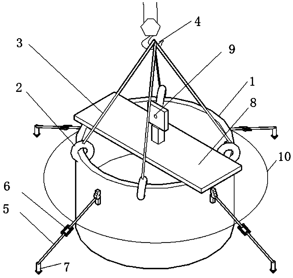
[0027] Such as figure 1 As shown, an installation structure for accurately burying a bored pile casing includes: a casing 1, a number of suspension rings 2 are arranged on the top of the cas...


PUM


Abstract

The invention discloses a mounting structure and mounting method for precisely burying a cast-in-situ bored pile protection barrel. The structure comprises the protection barrel, multiple lifting rings are arranged at the top of the protection barrel, the lifting rings are connected with lifting ropes, the other ends of the lifting ropes are connected with hoisting hooks, the side wall of the protection barrel is connected with multiple horizontal inhaul cables, and the other ends of the horizontal inhaul cables are fixed to the ground outside a foundation pit through ground anchors. The technical problems that in the prior art, the protection barrel locating precision is not high, and monitoring cannot be achieved during operation are solved.

Description

technical field [0001] The invention belongs to the technical field of construction, and in particular relates to an installation structure and an installation method for accurately embedding bored pile casings. Background technique [0002] At present, when the casing is buried, the center point of the pile position is generally first staked out on the ground, then the foundation pit is excavated, and then the center point is released at the bottom of the foundation pit (or stakes are set out around the foundation pit before excavation), and the casing is lifted by a crane It is lowered to the foundation pit for burial. During the lowering process, workers push and pull the casing according to the center point of the bottom of the foundation pit or the surrounding piles, so that the center of the casing coincides with the center of the pile position. Since the manual operation depends entirely on the experience level of the workers, and because the high casing height (1.5-3...

Claims


Application Information

Patent Timeline
IPC IPC(8): E02D7/00E02D13/04E02D13/06
CPCE02D7/00E02D13/04E02D13/06
Inventor 蒋凯张年丰方三陵
Owner CHINA FIRST METALLURGICAL GROUP
Learn More