Medical device with a nested lap joint and a fused conductive element and method for fabricating the same

a technology of conductive elements and lap joints, which is applied in the field of medical devices, can solve the problems of symptomatic and asymptomatic ailments, even death, limits, corrals, etc., and achieve the effects of less kinking, less risk of joint separation, and more reliable and durabl

Active Publication Date: 2018-11-22
ST JUDE MEDICAL CARDILOGY DIV INC
View PDF2 Cites 0 Cited by
  • Summary
  • Abstract
  • Description
  • Claims
  • Application Information

AI Technical Summary

Benefits of technology

[0015]A medical device and method for making the same in accordance with the present teachings is advantageous relative to conventional devices and methods. A medical device and method for making the same in accordance with the present teachings provide a more reliable and durable medical device with less kinking and a reduced risk of joint separation by spreading the loads over the various layers of the device. In addition, the method for making the device allows for more precise embedding of the conductive element and increased efficiency, which results in a decrease in cost.

Problems solved by technology

Arrhythmias can create a variety of conditions including irregular heart rates, loss of synchronous atrioventricular contractions, and stasis of blood flow in a chamber of a heart, which can lead to a variety of symptomatic and asymptomatic ailments and even death.
This lesion disrupts undesirable cardiac activation pathways and thereby limits, corrals, or prevents errant conduction signals that can form the basis for arrhythmias.
If the energy is released suddenly, the distal end of the catheter, which may be deflected by a steering mechanism, can be undesirably propelled with significant force.
Shaft compression can result in a loss of control for the medical practitioner and can complicate the positioning of the distal end of the catheter shaft at a desired location for a medical procedure.
In addition, medical personnel may rely on tactile feedback to attain and verify proper positioning of the catheter, and such feedback can be impaired by excessive compressibility.
In addition, the method for making the device allows for more precise embedding of the conductive element and increased efficiency, which results in a decrease in cost.

Method used


Image

  • Medical device with a nested lap joint and a fused conductive element and method for fabricating the same
  • Medical device with a nested lap joint and a fused conductive element and method for fabricating the same
  • Medical device with a nested lap joint and a fused conductive element and method for fabricating the same

Examples


Embodiment Construction

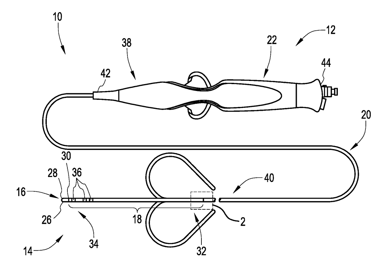
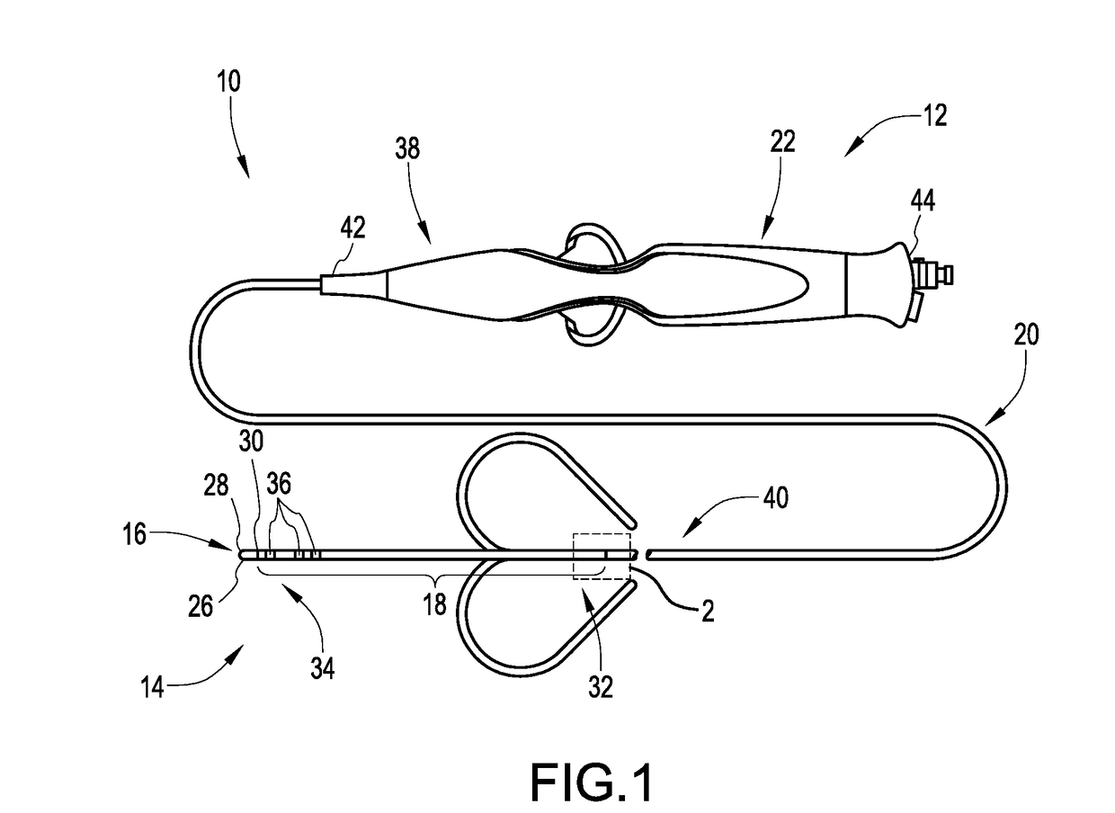
[0030]An electrophysiology catheter may include an elongate proximal shaft portion and a deflectable distal shaft portion. The connection between the proximal and distal shaft portions must be sufficient enough to withstand tensile loads and other stresses. The proximal shaft portion may be relatively stiff, while the distal deflectable shaft portion may be relatively less stiff. When the connection or joint between the proximal and distal shaft portions transitions stiffness abruptly, the catheter may exhibit a non-uniform curvature during deflection and have inequitable stress profiles. However, a joint that transitions stiffness gradually across the catheter length may result in a catheter having uniform curvature and equitable stress profiles. Moreover, having multiple bonded layers in the catheter may result in even more gradual stiffness transitions. In addition, when using rigid adhesives, it may be desirable to spread the bond joints out (since the adhesive may be more rigid...


PUM

PropertyMeasurementUnit
lengthaaaaaaaaaa
lengthaaaaaaaaaa
lengthaaaaaaaaaa

Abstract

A medical device for the diagnosis or treatment of tissue in a body and method for fabricating the same are provided. The device includes comprises a first shaft and a second shaft. The first shaft includes a longitudinal axis, and the second shaft includes a second shaft axial end disposed within the first shaft. The second shaft is connected to the first shaft by a first nested lap joint formed between the first shaft and the second shaft.

Description

CROSS-REFERENCE TO RELATED APPLICATIONS[0001]This application is a continuation of U.S. patent application Ser. No. 14 / 724,119, filed 28 May 2015, which claims the benefit of U.S. provisional application No. 62 / 008,180, filed 5 Jun. 2014, both of which are hereby incorporated by reference as though fully set forth herein.BACKGROUNDa. Technical Field[0002]This disclosure generally relates to a medical device for diagnosis or treatment of tissue in a body and method for fabricating the same. In particular, the instant disclosure relates to the joining of various members and / or components in shafts of a medical device.b. Background Art[0003]This background description is set forth below for the purpose of providing context only. Therefore, any aspects of this background description, to the extent that it does not otherwise qualify as prior art, is neither expressly nor impliedly admitted as prior art against the instant disclosure.[0004]Electrophysiology catheters are used in a variety...

Claims


Application Information

Patent Timeline
Patent Type & Authority Applications(United States)
IPC IPC(8): A61M25/01B29C65/14A61B5/04A61B18/14A61M25/00A61B5/00A61B5/01A61B5/042A61B17/00A61B17/32A61B18/00A61B18/02A61B18/20B29L31/00
CPCA61B2018/00071A61B17/320068A61B2018/00839A61B2018/0016A61B2017/00044A61M25/0012A61B5/6852A61B18/1492A61M25/0144A61M25/0147B29L2031/753A61B2018/00351B29C65/14A61B5/042A61B5/01A61M25/0009A61B5/04A61B2018/0212A61B2018/00821A61B2018/00357A61B18/201A61B2017/00526A61B5/283A61M25/005A61M25/0136A61M25/0138A61B5/24
Inventor TEGG, TROY T.HOUCK, ALEXANDER C.ARIAS-GONZALEZ, SALOMEHER, JOHN S.MOM, SOMALLY
Owner ST JUDE MEDICAL CARDILOGY DIV INC
Why Eureka
Try Eureka