Road pavement drainage structure and construction method thereof

A drainage structure and road pavement technology, which is applied to drainage structures, waterway systems, water supply devices, etc., to achieve the effects of convenient operation, reduced blockage, and simple structure

Active Publication Date: 2020-07-10
佛山市禅鸿建设工程有限公司
View PDF8 Cites 13 Cited by
  • Summary
  • Abstract
  • Description
  • Claims
  • Application Information

AI Technical Summary

Problems solved by technology

[0004] Aiming at the deficiencies of the prior art, the object of the present invention is to provide a drainage structure for municipal roads, which c

Method used


Image

  • Road pavement drainage structure and construction method thereof
  • Road pavement drainage structure and construction method thereof
  • Road pavement drainage structure and construction method thereof

Examples


Embodiment 1

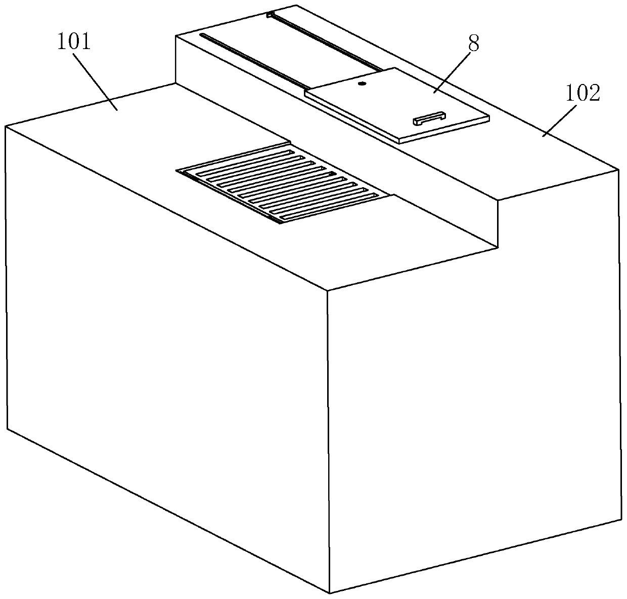
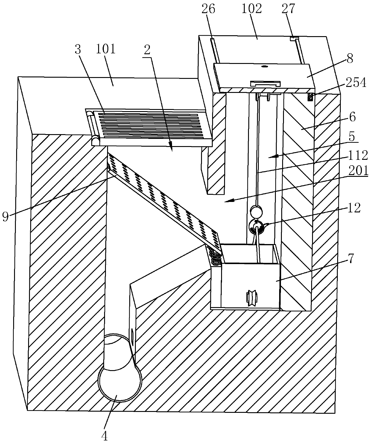
[0044] refer to figure 1 and figure 2 , is a road pavement drainage structure disclosed in the present invention, including a road main body 1 and a drainage pipe 4 arranged in the road main body 1, specifically, the road main body 1 includes a lane 101 and a sidewalk 102, and the sidewalk 102 is set higher than the lane 101, The side of the lane 101 near the sidewalk 102 is provided with a drainage well 2, the wellhead of the drainage well 2 is equipped with a drainage grille 3, the drainage pipe 4 is connected to the lower end of the drainage well 2, and the sidewalk 102 is provided with a drain that communicates with the ground. The square sewage collection well 5, the wellhead of the sewage collection well 5 slides along the horizontal direction and is equipped with a rectangular plate-shaped cover plate 8 for opening and closing the sewage collection well 5; at the same time, one side of the drainage well 2 is provided with a bridge that communicates with the road surfac...

Embodiment 2

[0055] A construction method for a road pavement drainage structure, comprising the following steps:

[0056] S1. Excavate the earthwork from top to bottom on the driveway 101, excavate the drainage well 2 vertically, excavate the earthwork from the top to the bottom on the sidewalk 102, and excavate the square sewage collection well 5 vertically. Laterally excavate the sewage hole 201 connected with the sewage collection well 5;

[0057] S2. Install the drainage pipe 4, excavate a groove horizontally at the bottom of the drainage well 2, lay the drainage pipe 4 in the groove, and make the water inlet of the drainage pipe 4 communicate with the bottom of the drainage well 2;

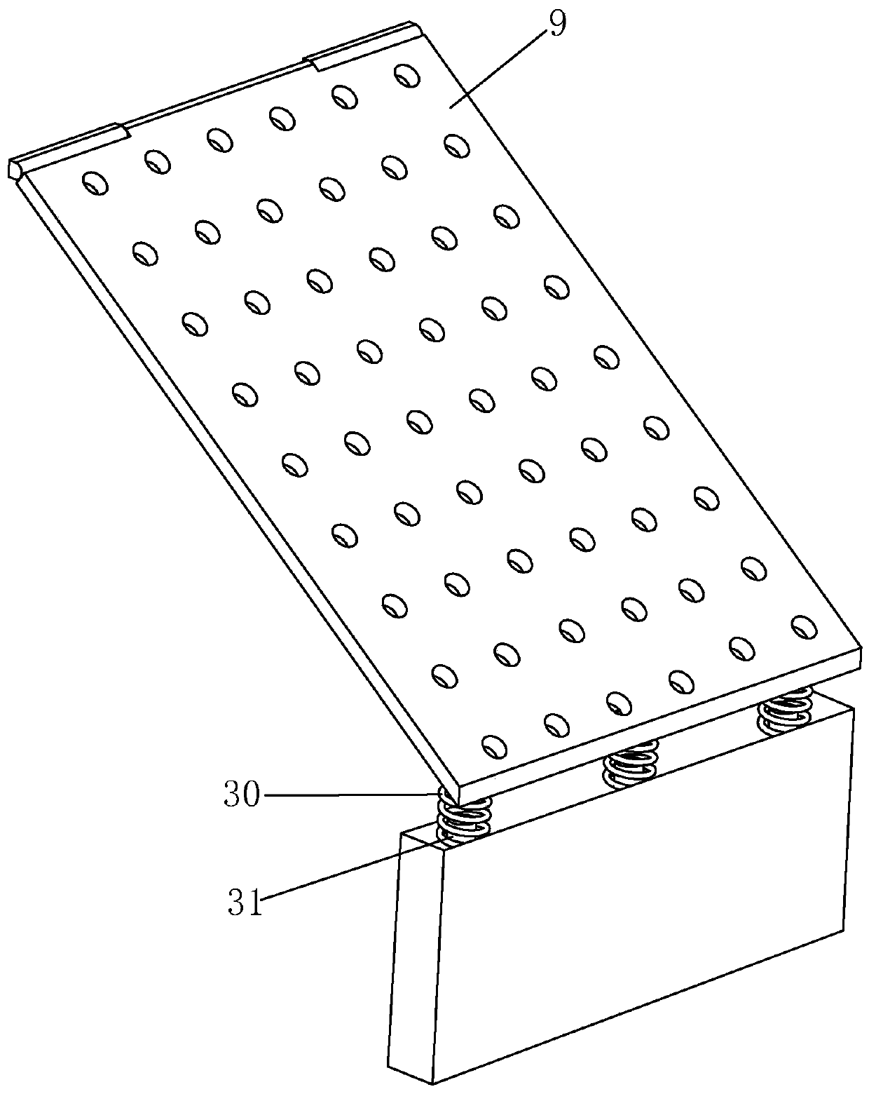
[0058]S3. Hinge one end of the filter plate 9 to the end of the drainage well 2 away from the sewage outlet, install a number of buffer springs 30 on the free end of the filter plate 9, and connect the other end of the buffer spring 30 to the wall of the drain hole 201 , so that the filter plate 9 is in...


PUM


Abstract

The invention relates to the technical field of road drainage, and particularly relates to a road pavement drainage structure and a construction method thereof. According to the technical scheme, theroad pavement drainage structure is characterized by comprising a road body and a drainage pipeline, wherein the road body comprises a lane and a sidewalk; a drainage well is arranged on the side, close to the sidewalk, of the lane; a drainage grating is arranged at a well opening of the drainage well; the drainage pipeline communicates with the lower end of the drainage well; a sewage collectionwell communicating with the ground is arranged on one side of the sidewalk; a cover plate is arranged at the sewage collection well in a sliding mode; a sewage discharge hole is formed in the drainagewell; a collection frame is contained at the well bottom of the sewage collection well; a mounting plate is arranged on the inner side wall of the sewage collection well; the mounting plate rotationally bears a rotating shaft; the rotating shaft is fixedly sleeved with a wire wheel; a steel wire rope is wound around the wire wheel; a lifting hook is arranged at the free end of the steel wire rope; and a hanging piece is fixedly connected to the collection frame. Sewage discharged by municipal roads can be effectively filtered, filtered garbage is collected and treated, and then the situationthat the drainage pipeline is blocked is reduced.

Description

technical field [0001] The invention relates to the technical field of road drainage, more specifically, it relates to a road surface drainage structure and a construction method thereof. Background technique [0002] With the development of urbanization, there are more and more road constructions in the city. For the safety of the road and the convenience of pedestrians on the road, there are drainage outlets on the road. Rainwater, therefore drainage is an essential part of road construction. [0003] However, in the prior art, due to the continuous increase of domestic garbage, a great deal of pressure has been added to the city's drainage and sewage pipes, which is likely to cause pipe blockage, especially when the rainwater increases in a large amount in summer, and a large amount of sediment will be mixed in the rainwater , leaves, domestic garbage, etc. enter the drainage pipes. The traditional drainage and sewage pipes are easily blocked by a large amount of garbage...

Claims


Application Information

Patent Timeline
IPC IPC(8): E03F5/04E03F3/06E03F3/02
CPCE03F3/02E03F3/06E03F5/0403E03F5/0404
Inventor 陈娟吟
Owner 佛山市禅鸿建设工程有限公司
Why Eureka
Try Eureka