High-stability protection device for high-rise building construction

A technology for building construction and protection devices, which is applied in the directions of construction, building structure, housing structure support, etc., can solve the problems of safety accidents, inconvenient adjustment of device size, difficulty in high-rise construction, etc., to ensure stability and reduce construction costs. Difficulty, the effect of reducing the risk of security incidents

Inactive Publication Date: 2020-07-10
马新国
View PDF7 Cites 1 Cited by
  • Summary
  • Abstract
  • Description
  • Claims
  • Application Information

AI Technical Summary

Problems solved by technology

For this reason, an object of the present invention is to provide a kind of protection device for high-rise building construction with high stability, which is mainly used to solve the problem that high-rise construction is difficult and safety accidents are easy to occur during construction, and the size of the device is inconvenient to adjust.

Method used


Image

  • High-stability protection device for high-rise building construction
  • High-stability protection device for high-rise building construction
  • High-stability protection device for high-rise building construction

Examples


Embodiment 1

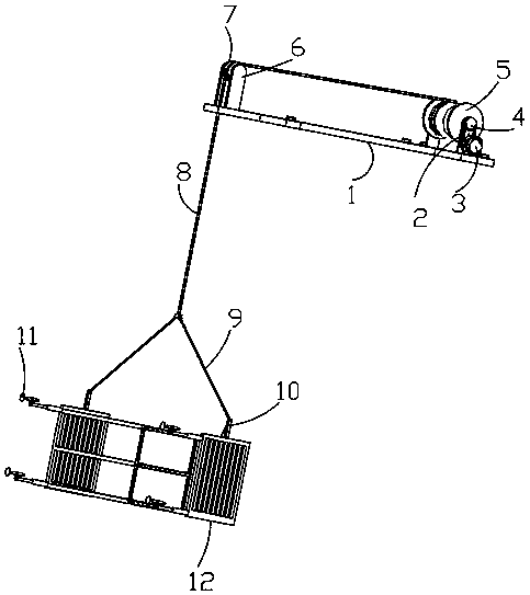
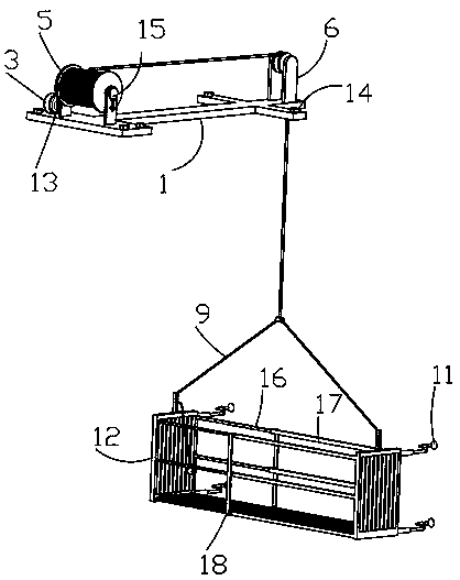
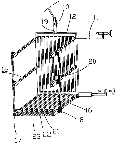
[0030] like Figure 1-7 A protective device for high-stable high-rise building construction shown includes a mounting frame 1, a drive motor 3, a first steel rope 8, and a second steel rope 9, and the mounting frame 1 is threaded through symmetrically opened threaded holes to be used for the mounting frame. 1 fixed mounting bolts 14, the support plate 6 is symmetrically and fixedly connected to the mounting frame 1, the guide roller 7 and the winding roller 5 are rotatably connected between the support plates 6 through fixedly connected bearings, and the right end of the rotating shaft of the winding roller 5 is fixedly connected There is a driven ring gear 4, the driven ring gear 4 is meshed with the chain 2, the output end of the driving motor 3 is fixedly connected with the driving ring gear 13 meshed with the chain 2, and the left end of the shaft of the winding roller 5 is provided with a The second fixed structure 15 for the brake of the roller 5, the winding roller 5 is...

Embodiment 2

[0032] Embodiment 2 is a further improvement to Embodiment 1.

[0033] like Figure 1-7A protective device for high-stable high-rise building construction shown includes a mounting frame 1, a drive motor 3, a first steel rope 8, and a second steel rope 9, and the mounting frame 1 is threaded through symmetrically opened threaded holes to be used for the mounting frame. 1 fixed mounting bolts 14, the support plate 6 is symmetrically and fixedly connected to the mounting frame 1, the guide roller 7 and the winding roller 5 are rotatably connected between the support plates 6 through fixedly connected bearings, and the right end of the rotating shaft of the winding roller 5 is fixedly connected There is a driven ring gear 4, the driven ring gear 4 is meshed with the chain 2, the output end of the driving motor 3 is fixedly connected with the driving ring gear 13 meshed with the chain 2, and the left end of the shaft of the winding roller 5 is provided with a The second fixed str...

Embodiment 3

[0035] Embodiment 3 is a further improvement to Embodiment 1.

[0036] like Figure 1-7 A protective device for high-stable high-rise building construction shown includes a mounting frame 1, a drive motor 3, a first steel rope 8, and a second steel rope 9, and the mounting frame 1 is threaded through symmetrically opened threaded holes to be used for the mounting frame. 1 fixed mounting bolts 14, the support plate 6 is symmetrically and fixedly connected to the mounting frame 1, the guide roller 7 and the winding roller 5 are rotatably connected between the support plates 6 through fixedly connected bearings, and the right end of the rotating shaft of the winding roller 5 is fixedly connected There is a driven ring gear 4, the driven ring gear 4 is meshed with the chain 2, the output end of the driving motor 3 is fixedly connected with the driving ring gear 13 meshed with the chain 2, and the left end of the shaft of the winding roller 5 is provided with a The second fixed st...


PUM


Abstract

The invention relates to a high-stability protection device for high-rise building construction in the field of protection devices for building construction. The device comprises a mounting rack, wherein the mounting bracket is provided with mounting bolts; support plates are arranged on the mounting rack; the support plates are provided with a guide roller and a winding roller; the winding rolleris provided with a driven gear ring; the driven gear ring is provided with a chain; a drive motor is provided with a driving ring gear; the winding roller is provided with a second fixing structure;the winding roller is provided with a first steel cable; the first steel cable is provided with a second steel cable; the second steel cable is provided with straight plates; each straight plate is provided with a grid plate; each grid plate is provided with first fixing structures; each grid plate is provided with sliding plates and sleeve plates which are slidably connected; each sliding plate is provided with positioning holes; each sleeve plate is provided with a second spring; each second spring is provided with an insertion rod; each insertion rod is connected to the corresponding positioning hole in an inserted mode; each grid plate is provided with a bottom plate and an L-shaped plate; and each bottom plate is movably connected to the corresponding L-shaped plate. According to theprotection device, a distance between the two groups of grid plates can be adjusted through cooperation of the bottom plates and the L-shaped plates and the cooperation of the sleeve plates and the sliding plates, so that the size of the device can be adjusted according to the requirements for the construction environment, and the device is convenient for actual use.

Description

technical field [0001] The invention relates to the field of protective devices for building construction, in particular to a protective device for high-rise building construction with high stability. Background technique [0002] High-rise buildings are high-rise buildings. According to tradition, buildings with more than 9 floors and elevators can be called high-rise buildings. However, in modern society, due to the increasing number and height of high-rise buildings, a new definition has been added to high-rise buildings. Generally, it is called a high-rise building with more than 18 floors, and it can be called a building with a height of 100 meters or more than 30 floors. Supertall buildings or skyscrapers. In mainland China, building codes stipulate that buildings with a height of more than 100 meters are super high-rise buildings; [0003] Building construction refers to the production activities in the implementation stage of engineering construction. It is the con...

Claims


Application Information

Patent Timeline
Patent Type & Authority Applications(China)
IPC IPC(8): E04G3/30E04G3/32E04G5/00E04G5/04E04G5/14
CPCE04G3/30E04G3/32E04G5/00E04G5/046E04G5/14
Inventor 马新国
Owner 马新国
Why Eureka
Try Eureka