
Two-dimensional array low-pollution combustion device without traditional cyclone

A combustion device, two-dimensional array technology, applied in combustion chambers, combustion methods, combustion equipment, etc., can solve the problems of low pollutant emission levels, difficulty in achieving, and increase NOx pollutant emissions, so as to reduce nitrogen oxide emissions, Avoid the effect of local high temperature and local low temperature

Active Publication Date: 2020-07-10
INST OF ENGINEERING THERMOPHYSICS - CHINESE ACAD OF SCI
View PDF11 Cites 4 Cited by
  • Summary
  • Abstract
  • Description
  • Claims
  • Application Information

AI Technical Summary

Problems solved by technology

The key to various combustion technologies is the method of achieving uniform fuel mixing and stable combustion. In the existing conventional annular combustor and multi-swirler schemes, each swirler has a nozzle and relatively independently organizes combustion and Mixing, the entire combustion chamber is equivalent to having multiple independent hot spots, which is easy to generate thermal NOx
Due to the requirements of space layout, the number of cyclones is limited, and the cyclone is circular, and the space between the cyclones cannot be fully utilized
This makes it difficult to mix the fuel and air sufficiently, so local high-temperature combustion must occur, thus increasing the emission of NOx pollutants
A lot of research has been carried out at home and abroad. The current low-emission combustor technologies mainly include lean fuel direct injection / multi-point injection technology, lean-burn premixed combustion technology, and double-ring premixed swirl combustion technology. The combustion chamber at the head of the swirler is based, so it cannot completely solve the above problems of the conventional multi-swirler combustion chamber
In addition, although the concave cavity trapped vortex combustion technology adopts a two-dimensional structure, in order to form a two-dimensional trapped vortex, a protruding concave cavity structure is arranged outside the main structure of the combustion chamber, which is not conducive to the overall layout and requires complex air flow organization. , to achieve a stable trapped vortex
[0003] In short, with the improvement of pollutant emission requirements, the current low-pollution combustion technology is limited by the technical route of traditional multi-cyclone combustion, and it is increasingly difficult to achieve lower pollutant emission levels. It is urgent to develop new low-pollution combustion technologies. combustion technology

Method used


Image

  • Two-dimensional array low-pollution combustion device without traditional cyclone
  • Two-dimensional array low-pollution combustion device without traditional cyclone
  • Two-dimensional array low-pollution combustion device without traditional cyclone

Examples


Embodiment Construction

[0016] In order to make the object, technical solution and advantages of the present invention clearer, the present invention will be further described in detail below in conjunction with specific embodiments and with reference to the accompanying drawings.

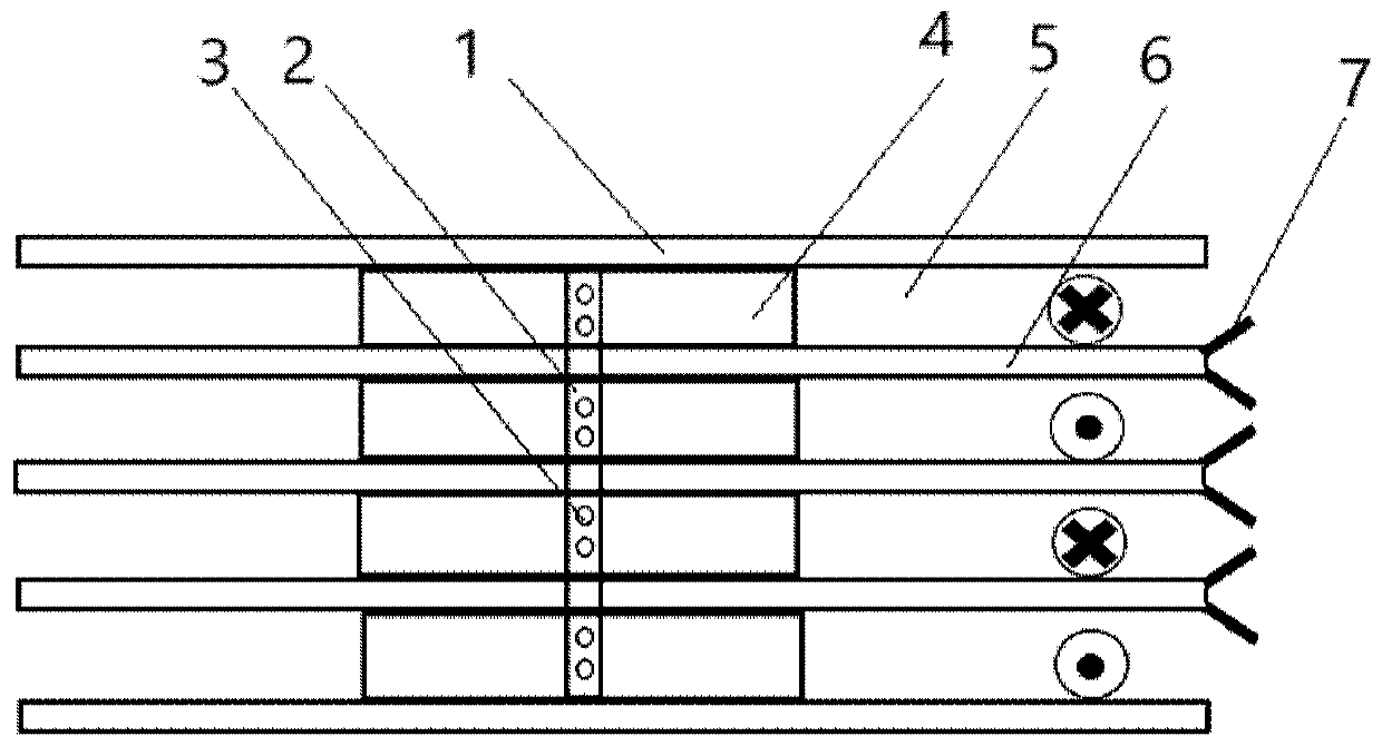
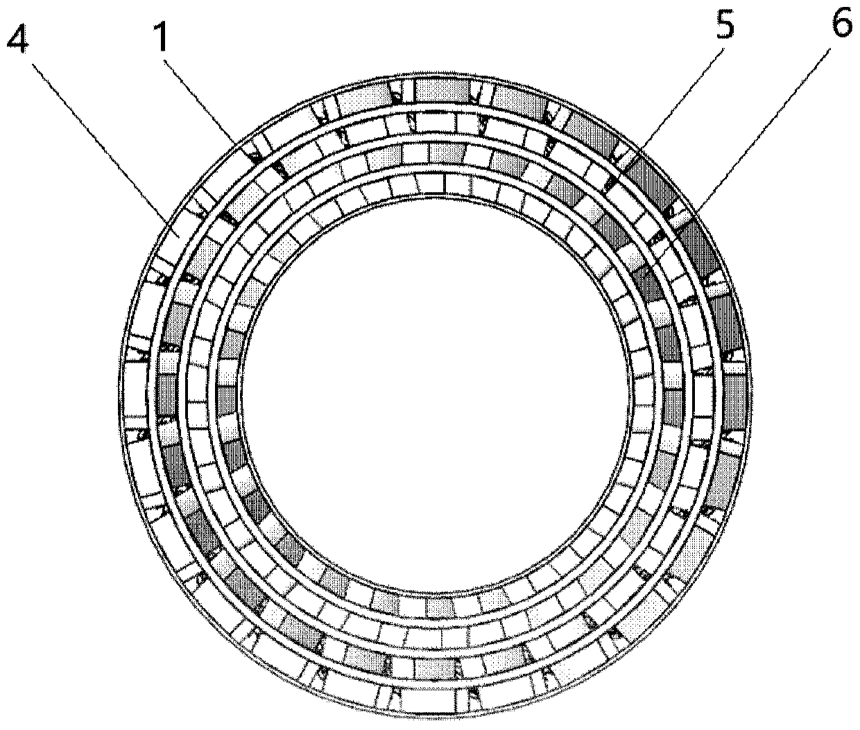
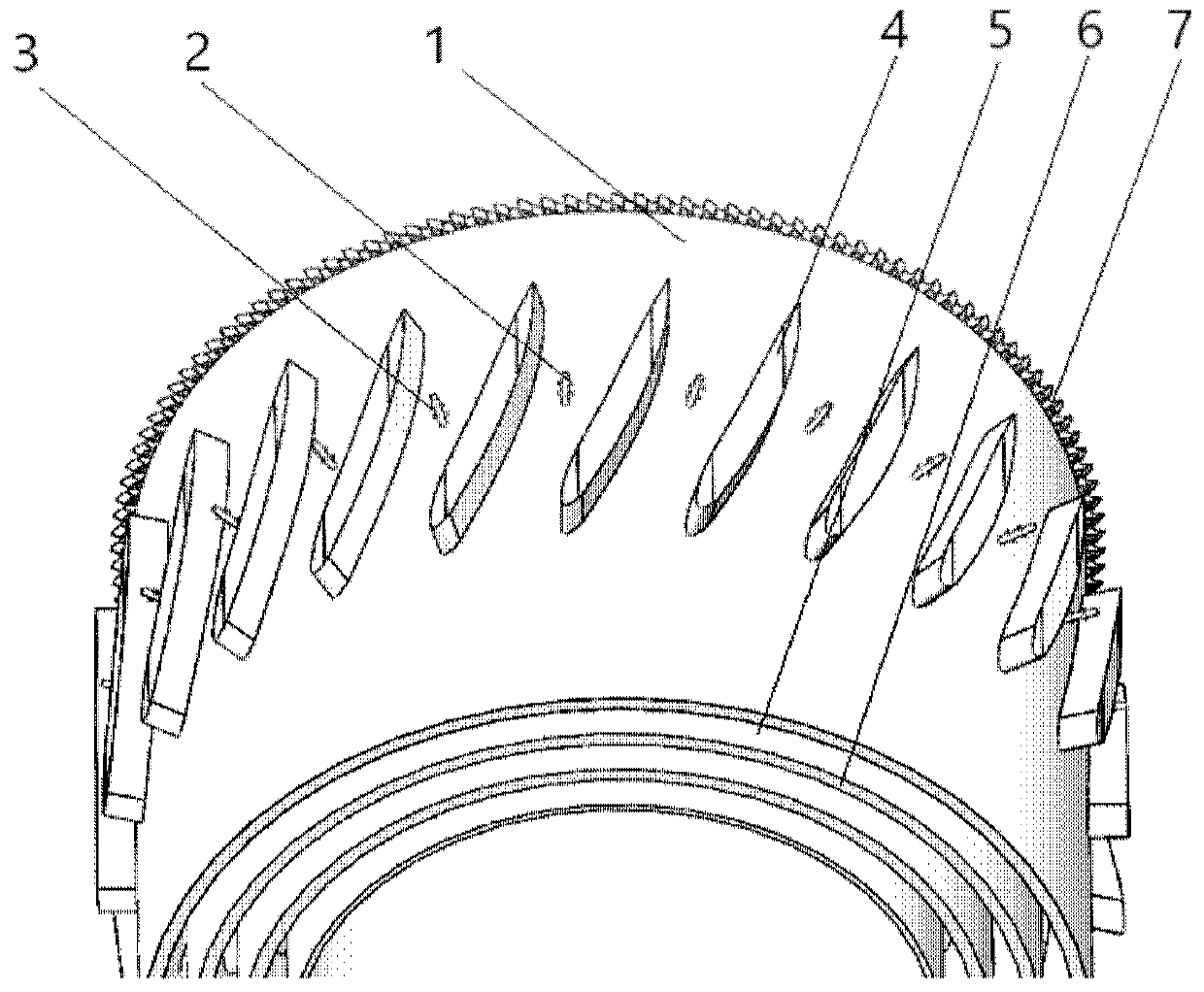
[0017] The invention discloses a two-dimensional array low-pollution combustion device without a traditional swirler, which comprises an annular combustion chamber head, the annular combustion chamber head is divided into a plurality of annular air flow channels, and the outlet of the annular air flow channel is provided with a flame stabilizing structure; a plurality of guide vanes are circumferentially distributed in each annular air flow channel; fuel pipes are arranged between the guide vanes.

[0018] In some embodiments of the present invention, the airflow in the annular airflow channel flows independently;

[0019] In some embodiments of the present invention, the guide vanes in adjacent annular air flow passages ...


PUM


Abstract

The invention discloses a two-dimensional array low-pollution combustion device without a traditional cyclone. The two-dimensional array low-pollution combustion device without the traditional cyclonecomprises a ring combustion chamber head, the ring combustion chamber head is separated into a plurality of ring air flow channels, and flame-stabilizing structures are aranged on outlets of the ringair flow channels; a plurality of guide blades are arranged in each ring air flow channel in the circumferential direction; and fuel pipelines are arranged between the guide blades. The two-dimensional array low-pollution combustion device without the traditional cyclone makes full use of the head space of the combustion chamber to form a uniform premixed combustion mode, at the same time, by increasing the number of fuel nozzles, the multi-point injection is realized, the local high temperature is avoided, and the emission of thermal NOx pollutants is reduced.

Description

technical field [0001] The invention belongs to the technical field of aero-engines and gas turbines, and in particular relates to a two-dimensional array low-pollution combustion device without traditional swirlers. Background technique [0002] Aeroengines and some gas turbines generally adopt the integral structure of annular combustors and multi-swirlers. In recent years, with the continuous improvement of pollutant emission standards in the energy and power fields, reducing pollutant emissions has become an important indicator for designing combustion chambers, among which NOx is the most important pollutant. The main purpose of low-pollution combustion technology is to organize the uniform combustion of fuel and air, avoid local hot spots and high-temperature combustion in a near-stoichiometric state, thereby reducing the production of a large amount of thermal NOx at high temperatures. The key to various combustion technologies is the method of achieving uniform fuel...

Claims


Application Information

Patent Timeline
Patent Type & Authority Applications(China)
IPC IPC(8): F23R3/52F23R3/14F23R3/18F23R3/28
CPCF23R3/14F23R3/18F23R3/28F23R3/286F23R3/52
Inventor 王宝瑞王岩赵玮杰王岳
Owner INST OF ENGINEERING THERMOPHYSICS - CHINESE ACAD OF SCI
Learn More