Adjustable range hood and adjusting method thereof

A range hood and adjustable technology, which is applied in the fields of removing oil fume, heating mode, and household heating, can solve the problems of inconvenient cleaning, increased cleaning difficulty, and laboriousness, and achieve the effect of convenient treatment.

Inactive Publication Date: 2020-07-10
南京华成厨具有限公司
View PDF0 Cites 2 Cited by
  • Summary
  • Abstract
  • Description
  • Claims
  • Application Information

AI Technical Summary

Problems solved by technology

[0004] However, the side-suction range hood is also very inconvenient when cleaning because its installation position is relatively front relative to the user.
Because there is a stove and kitchen utensils in the middle, the side suction range hood has no advantage when cleaning: if the user stands directly on the ground to clean it, it is difficult to reach the side suction range hood, and the cleaning difficulty increases; With the help of benches and other heightening materials, the operator needs to bend down to handle it, which is quite strenuous

Method used


Image

  • Adjustable range hood and adjusting method thereof
  • Adjustable range hood and adjusting method thereof
  • Adjustable range hood and adjusting method thereof

Examples


Embodiment 1

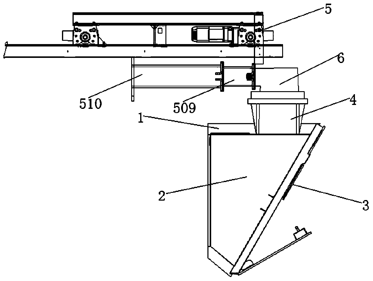
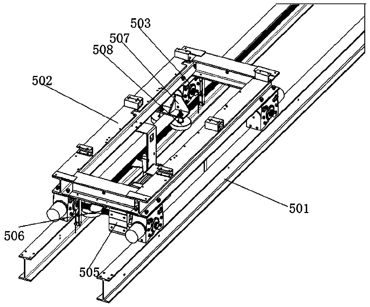
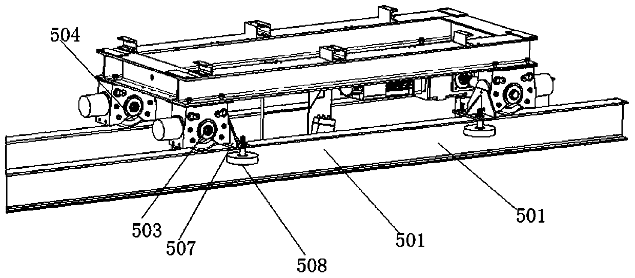
[0054] First, if figure 1 As shown, the adjustable range hood includes: a housing 1 , an exhaust box 2 , a smoke collecting hood 3 , a smoke exhaust pipe 4 and a moving mechanism 5 . The fume collecting hood 3 is fixed obliquely at the front and lower side of the can, and the exhaust box 2 is fixedly installed inside the housing 1 and corresponds to the fume collecting hood 3 for collecting oil fumes. The smoke exhaust pipe 4 is fixed above the housing 1 and communicates with the exhaust box 2 for discharging the collected oil fumes from the smoke exhaust pipe 4 . In order to regulate the distance between the casing 1 and the user, a moving mechanism 5 is fixedly arranged on the wall, and the moving mechanism 5 is connected to the top of the casing 1 by transmission. The moving mechanism 5 Used to control the distance between the housing 1 and the user; when the range hood is in use, the housing 1 is located at the end of the moving mechanism 5, that is, the rear wall of the ...

Embodiment 2

[0074] Based on the above-mentioned embodiment 1, the range hood is pushed to the front of the stove for cleaning. However, in the existing cleaning process, the internal exhaust box 2 is often wiped by taking off the fume collecting hood 3, and this cleaning method needs very frequent processing at first, and if the interval is longer, it will lead to the accumulation of oil fumes. The oil accumulated in the fume collecting hood 3 inside, plus the accumulation of time and the effect of gravity, the oil will drip out, causing the growth of bacteria on the stove. Therefore, the above cleaning is not thorough enough.

[0075] Utilizing the idea of ​​bringing the range hood close to the user proposed in Embodiment 1, a corresponding exhaust box 2 is designed that can collect and treat oil stains well.

[0076] Specifically, such as Figure 5 to Figure 6 As shown, the exhaust box 2 is provided with a smoking mechanism, and the smoking mechanism includes: a housing 101, the housi...


PUM


Abstract

The invention discloses an adjustable range hood and an adjusting method thereof, and belongs to the technical field of range hoods. The range hood comprises a shell, an air draft box arranged insidethe shell, an exhaust fume collecting hood obliquely installed on the front lower part of the shell, a fume exhaust pipe installed on the upper part of the shell and communicating with the air draft box, and a moving mechanism fixed to a wall, wherein the moving mechanism is in transmission connection with the top of the shell and used for controlling the distance between the shell and a user. According to the adjustable range hood and the adjusting method thereof, a mechanism capable of adjusting the distance between the side suction type range hood and the user is installed at the top of theside suction type range hood, so that the range hood is conveniently adjusted to a proper position for cleaning during cleaning, the sealing performance of the fume exhaust pipe is not influenced inan adjusting process, and residual oil inside the range hood can be conveniently treated.

Description

technical field [0001] The invention belongs to the technical field of range hoods, in particular to an adjustable range hood and an adjustment method thereof. Background technique [0002] At present, range hoods have been widely used in kitchens, and are divided into two types according to their installation methods: side suction range hoods and top suction range hoods. [0003] The top-suction range hood has disadvantages in height during use, that is, it is easy to hit the user's head. Therefore, the side suction range hood has become the choice of young people today. The side-suction range hood is installed on the wall in front of the stove, and the oil-absorbing surface is inclined, so the problems caused by the top-suction range hood will not occur. [0004] However, the side-suction range hood is also very inconvenient to clean because it is installed in a front position relative to the user. Because there is a stove and kitchen utensils in the middle, the side su...

Claims


Application Information

Patent Timeline
Patent Type & Authority Applications(China)
IPC IPC(8): F24C15/20
CPCF24C15/2092
Inventor 胡明中
Owner 南京华成厨具有限公司
Why Eureka
Try Eureka