

Electric control compression testing machine and testing method for in-situ imaging by using high-energy X-rays
A compression test, X-ray technology, applied in the use of wave/particle radiation for material analysis, the use of stable tension/pressure test material strength, instruments, etc., to achieve the effect of light weight, large load, and good compatibility
Pending Publication Date: 2020-07-10
SOUTHWEST JIAOTONG UNIV +4
View PDF0 Cites 1 Cited by
- Summary
- Abstract
- Description
- Claims
- Application Information
AI Technical Summary
Problems solved by technology
[0006] Considering the above problems, the present invention provides an electronically contro
Method used
View moreImage
Smart ImageViewing Examples

Examples
 PUM
 Abstract
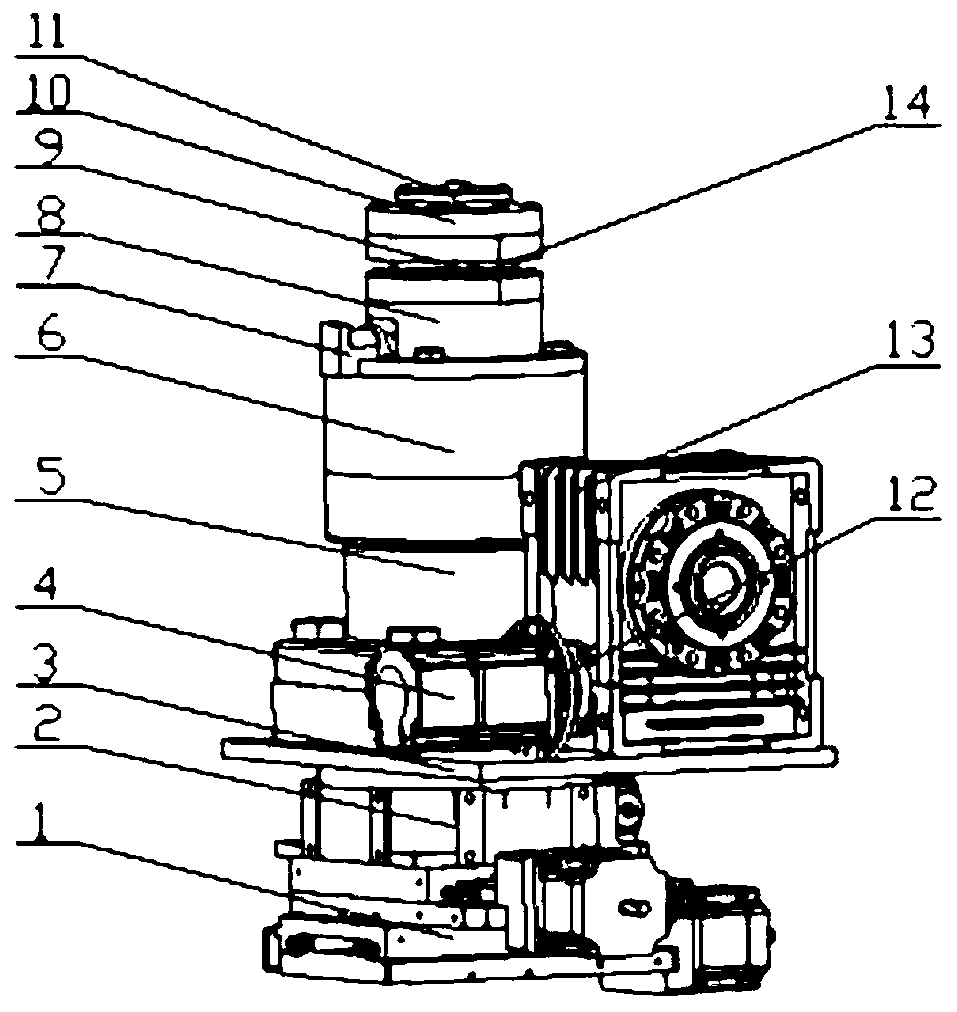
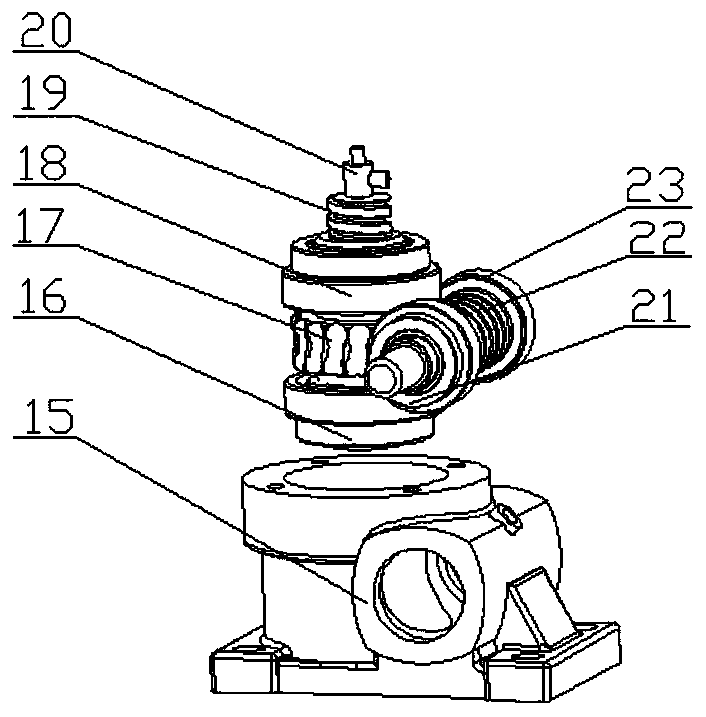
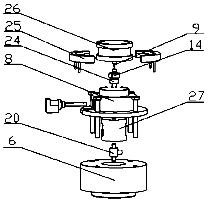
The invention discloses an electric control compression testing machine and testing method for in-situ imaging by using high-energy X-rays. A high-precision servo motor is adopted for actuation; the rotary motion of the motor is converted into the up-and-down linear motion of the lower clamp by utilizing a two-stage worm gear reducer; a sample is fixed through the upper clamp and the lower clamp,compressive stress is applied to the sample through displacement control of the lower clamp, loads and displacement borne by the sample in the testing process are collected in real time through the miniature dynamic force sensor and the laser vibrometer, and closed-loop control over the testing machine is achieved through the control unit. The testing machine disclosed by the invention is an in-situ compression material testing device which has the characteristics of high precision, large load, small size, light weight, capability of realizing monotonous compression and the like; good compatibility with a synchrotron radiation light source test platform can be realized, the requirements of a sample platform on weight and size are met, and the internal structure and typical defects of a material under various monotonous loading stress levels can be monitored in real time.
Description
technical field [0001] The invention belongs to the field of in-situ imaging control test equipment, and in particular relates to an electronically controlled compression testing machine and a test method for in-situ imaging with high-energy X-rays. Background technique [0002] High-energy X-ray computed tomography technology has submicron space and microsecond time resolution and excellent detection capabilities of hundreds of keV, which is several orders of magnitude higher than the test level of conventional industrial X-ray machines, making it possible to detect It is possible to observe the evolution of the internal pore structure of materials, which brings unprecedented opportunities for the study of mesoscopic mechanical properties of metal materials and composite materials. At present, there are relatively few domestic studies on the destruction process of the internal pore structure of metal materials and composite materials using high-energy X-ray computerized tom...
Claims
Login to View More Application Information
Patent Timeline
 IPC IPC(8): G01N23/046G01N3/08G01N3/06G01N3/04G01N15/08
CPCG01N3/04G01N3/06G01N3/08G01N15/0806G01N15/0826G01N23/046G01N2203/0019G01N2203/0048G01N2203/0075G01N2203/0298G01N2203/0641
Inventor吴圣川谢成吴正凯胡雅楠康国政张海鸥王桂兰赵晋津张博李玮洁葛敬冉杨绍普梁军黄海明
OwnerSOUTHWEST JIAOTONG UNIV