Optical imaging lens

An optical imaging lens and lens technology, applied in optics, optical components, instruments, etc., can solve the problems of long optical total length and the inability of mobile phones to meet ultra-thin, and achieve the effect of shortening horizontal distance and vertical distance.

Pending Publication Date: 2020-07-10
ZHEJIANG SUNNY OPTICAL CO LTD
View PDF0 Cites 0 Cited by
  • Summary
  • Abstract
  • Description
  • Claims
  • Application Information

AI Technical Summary

Problems solved by technology

If the conventional coaxial telephoto design is used, in order to meet the long focal length of the telephoto lens, the total opt

Method used


Image

  • Optical imaging lens
  • Optical imaging lens
  • Optical imaging lens

Examples


Embodiment 1

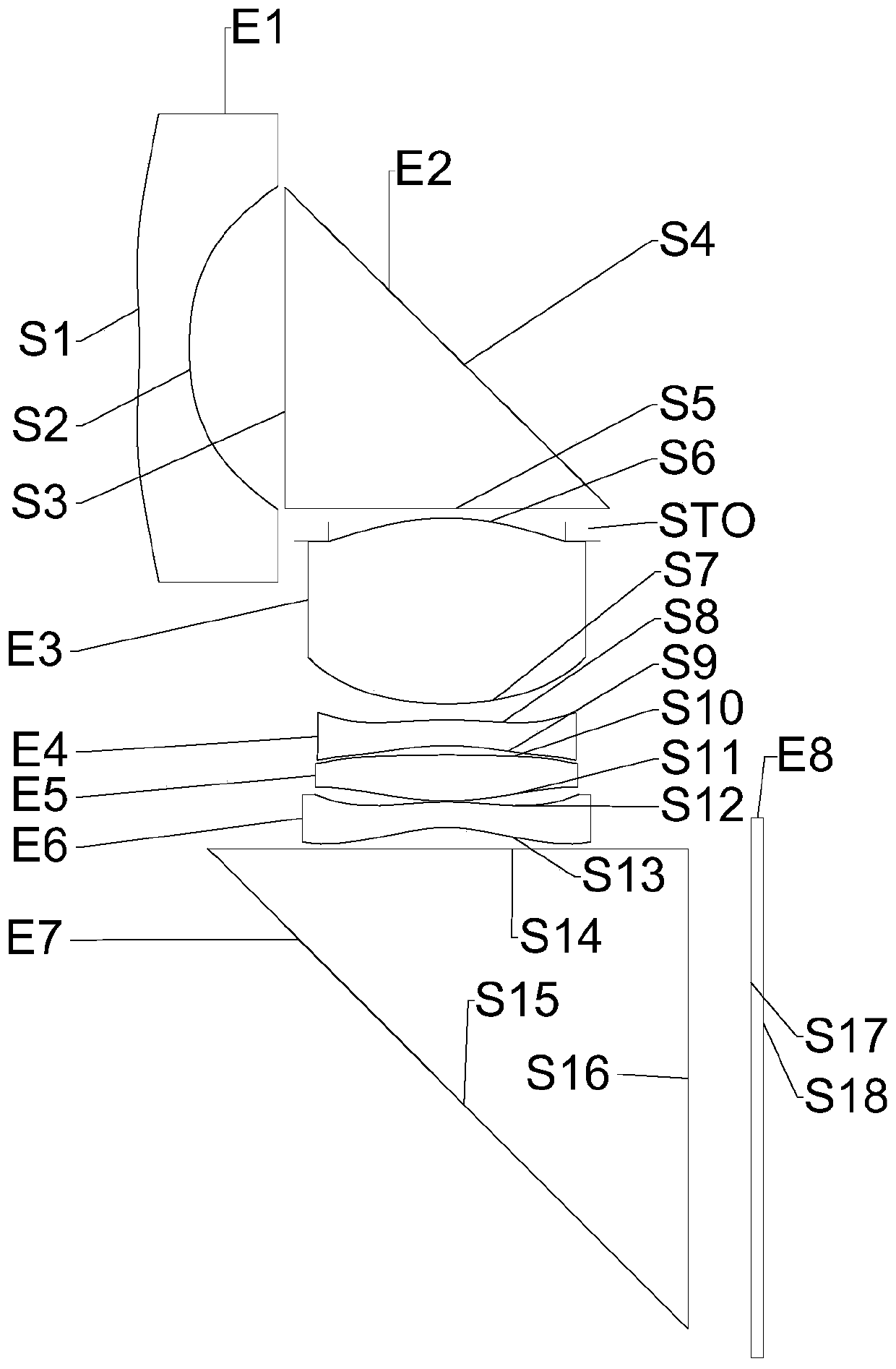
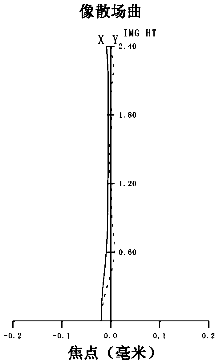
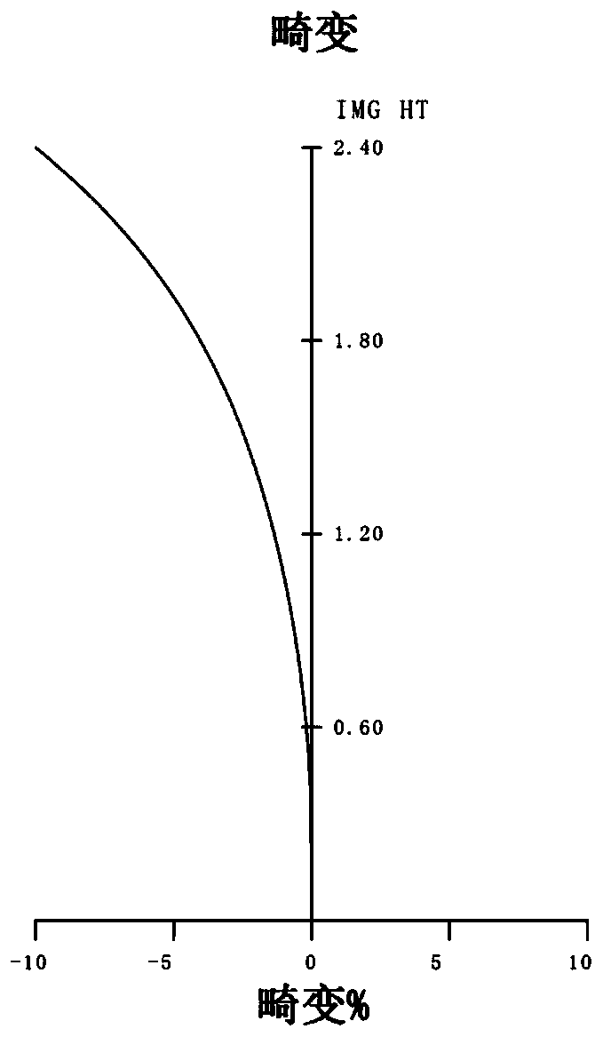
[0065] Refer to the following Figure 1 to Figure 2C An optical imaging lens according to Embodiment 1 of the present application is described. figure 1 is a schematic diagram showing the structure of an optical imaging lens according to Embodiment 1 of the present application.

[0066] Such as figure 1 As shown, the optical imaging lens includes in sequence from the object side to the image side along the optical axis: the first lens E1, the first prism E2, the diaphragm STO, the second lens E3, the third lens E4, the fourth lens E5, the fifth lens Lens E6, second prism E7, filter E8.

[0067]The first lens E1 has negative refractive power, its object side S1 is concave, and its image side S2 is concave. The incident surface S3, reflective surface S4, and outgoing surface S5 of the first prism E2 are all spherical surfaces, and the reflective surface S4 forms an angle of 45° with the optical axis, so that the light incident perpendicular to the incident surface S3 of the f...

Embodiment 2

[0079] Refer to the following Figure 3 to Figure 4C An optical imaging lens according to Embodiment 2 of the present application is described. image 3 is a schematic diagram showing the structure of an optical imaging lens according to Embodiment 2 of the present application.

[0080] Such as image 3 As shown, the optical imaging lens includes in sequence from the object side to the image side along the optical axis: the first lens E1, the first prism E2, the diaphragm STO, the second lens E3, the third lens E4, the fourth lens E5, the fifth lens Lens E6, second prism E7, filter E8.

[0081] The first lens E1 has negative refractive power, its object side S1 is concave, and its image side S2 is concave. The incident surface S3, reflective surface S4, and outgoing surface S5 of the first prism E2 are all spherical surfaces, and the reflective surface S4 forms an angle of 45° with the optical axis, so that the light incident perpendicular to the incident surface S3 of the ...

Embodiment 3

[0091] Refer to the following Figure 5 to Figure 6C An optical imaging lens according to Embodiment 3 of the present application is described. Figure 5 is a schematic diagram showing the structure of an optical imaging lens according to Embodiment 3 of the present application.

[0092] Such as Figure 5 As shown, the optical imaging lens includes in sequence from the object side to the image side along the optical axis: the first lens E1, the first prism E2, the diaphragm STO, the second lens E3, the third lens E4, the fourth lens E5, the fifth lens Lens E6, second prism E7, filter E8.

[0093] The first lens E1 has negative refractive power, its object side S1 is concave, and its image side S2 is concave. The incident surface S3, reflective surface S4, and outgoing surface S5 of the first prism E2 are all spherical surfaces, and the reflective surface S4 forms an angle of 45° with the optical axis, so that the light incident perpendicular to the incident surface S3 of th...


PUM


Abstract

The invention discloses an optical imaging lens. The optical imaging lens sequentially comprises a first lens with negative focal power; a first prism which comprises an incident surface, a reflectingsurface and an emergent surface, and the included angle between the reflecting surface and the optical axis is 45 degrees; a diaphragm; a second lens having positive focal power; a third lens havingfocal power; a fourth lens having positive focal power; a fifth lens having negative focal power; and a second prism which comprises an incident surface, a reflecting surface and an emergent surface,and the included angle between the reflecting surface and the optical axis is 45 degrees; wherein the total effective focal length f of the optical imaging lens and the maximum field angle FOV of theoptical imaging lens meet the condition that 2.50 mm < f * tan2 (FOV/2) < 4.00 mm.

Description

technical field [0001] The present application relates to the field of optical elements, and specifically relates to an optical imaging lens including five lenses and a double prism structure. Background technique [0002] Recently, most mobile phones on the market have a 3+1 lens configuration including a large image lens, a wide-angle lens, a telephoto lens and a TOF lens. zoom capability. If the conventional coaxial telephoto design is used, in order to meet the long focal length of the telephoto lens, the total optical length (TTL) of the lens will be lengthened, which may make the mobile phone unable to meet the ultra-thin feature. Therefore, an optical imaging lens with prism catadioptric performance emerges at the historic moment, which can effectively reduce the length of the mobile phone lens in the incident direction of light. [0003] Different from the optical imaging system of single prism, this technical solution is an optical imaging system of double prism, ...

Claims


Application Information

Patent Timeline
IPC IPC(8): G02B13/00G02B13/06G02B13/18
CPCG02B13/0065G02B13/0045G02B13/06G02B13/18G02B13/02G02B27/0025G02B15/145511G02B15/145515G02B9/60
Inventor 李龙闻人建科戴付建赵烈烽
Owner ZHEJIANG SUNNY OPTICAL CO LTD
Why Eureka
Try Eureka