Cooling control method and device based on CNC machine tool

A numerical control machine tool and cooling control technology, applied in the direction of digital control, program control, electrical program control, etc., can solve the problems of low water spray efficiency of CNC machine tools, inability to control water spray, automatic adjustment, etc.

Active Publication Date: 2021-07-06
ZHUHAI GREE INTELLIGENT EQUIP CO LTD +1
View PDF0 Cites 0 Cited by
  • Summary
  • Abstract
  • Description
  • Claims
  • Application Information

AI Technical Summary

Problems solved by technology

[0004] Embodiments of the present invention provide a cooling control method and device based on a numerically controlled machine tool, to at least solve the problem in the related art that the water spray control of the numerically controlled machine tool cannot be automatically adjusted according to actual needs during the automatic processing of the numerically controlled machine tool, resulting in relatively low water spray efficiency of the numerically controlled machine tool. low technical issues

Method used


Image

  • Cooling control method and device based on CNC machine tool
  • Cooling control method and device based on CNC machine tool
  • Cooling control method and device based on CNC machine tool

Examples


Embodiment 1

[0027] According to an embodiment of the present invention, a method embodiment of a cooling control method based on a numerically controlled machine tool is provided. It should be noted that the steps shown in the flow chart of the accompanying drawings can be implemented in a computer system such as a set of computer-executable instructions and, although a logical order is shown in the flowcharts, in some cases the steps shown or described may be performed in an order different from that shown or described herein.

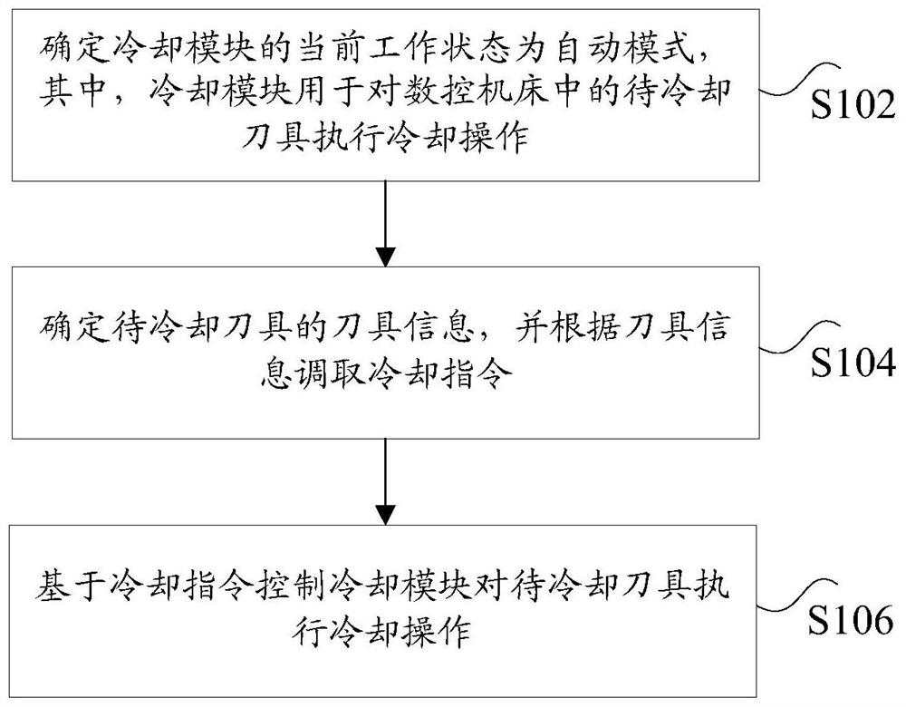
[0028] figure 1 It is a flowchart of a cooling control method based on a numerically controlled machine tool according to an embodiment of the present invention, such as figure 1 As shown, the cooling control method based on the CNC machine tool includes the following steps:

[0029] In step S102, it is determined that the current working state of the cooling module is an automatic mode, wherein the cooling module is used to perform a cooling operation on the to...

Embodiment 2

[0047] According to another aspect of the embodiment of the present invention, a cooling control device based on a numerically controlled machine tool is also provided, Figure 4 is a schematic diagram of a cooling control device based on a numerically controlled machine tool according to an embodiment of the present invention, such as Figure 4 As shown, the cooling control device based on a CNC machine tool includes: a first determination unit 41 , a second determination unit 43 and a control unit 45 . The cooling control device based on the numerical control machine tool will be described in detail below.

[0048] The first determination unit 41 is configured to determine that the current working state of the cooling module is an automatic mode, wherein the cooling module is used to perform a cooling operation on the tool to be cooled in the numerically controlled machine tool.

[0049] The second determining unit 43 is configured to determine tool information of the tool ...

Embodiment 3

[0058] According to another aspect of the embodiments of the present invention, there is also provided a storage medium, which is characterized in that the storage medium includes a stored program, wherein the program executes any one of the cooling control methods based on a numerically controlled machine tool described above.


PUM


Abstract

The invention discloses a cooling control method and device based on a numerical control machine tool. Wherein, the method includes: determining that the current working state of the cooling module is an automatic mode, wherein the cooling module is used to perform a cooling operation on the tool to be cooled in the CNC machine tool; determining the tool information of the tool to be cooled, and calling the cooling module according to the tool information command; based on the cooling command, the cooling module is controlled to perform a cooling operation on the tool to be cooled. The invention solves the technical problem in the related art that the water spraying control of the numerical control machine tool cannot be automatically adjusted according to the actual demand in the automatic processing process of the numerical control machine tool, resulting in low water spraying efficiency of the numerical control machine tool.

Description

technical field [0001] The invention relates to the technical field of numerical control machine tool control, in particular to a cooling control method and device based on a numerical control machine tool. Background technique [0002] In the water spray control method of traditional CNC machine tools, the machine tool generally adjusts the bamboo tube to spray water on the tip of the tool manually. However, in the actual processing process, many kinds of tools are required for automatic processing, for example, long props and short tools, so that the water spray cannot be accurately aimed at the tip of the tool, and the cooling effect is greatly reduced, making the blade and knife grains and other tools The service life of parts is greatly reduced, causing unnecessary losses. [0003] Aiming at the problem in the above-mentioned related technologies that the water spray control of the CNC machine tool cannot be automatically adjusted according to actual needs during the a...

Claims


Application Information

Patent Timeline
Patent Type & Authority Patents(China)
IPC IPC(8): G05B19/414B23Q11/10
CPCB23Q11/10G05B19/4147G05B2219/31182
Inventor 王占军熊坤张博周昊晖黎运尧杨建新
Owner ZHUHAI GREE INTELLIGENT EQUIP CO LTD
Why Eureka
Try Eureka