
Camera module and electronic equipment

A technology for camera modules and electronic equipment, applied in TVs, electrical components, color TVs, etc., which can solve problems such as high requirements for power devices, unfavorable fast zooming, and heavy weight of lens groups

Active Publication Date: 2020-07-10
GUANGDONG OPPO MOBILE TELECOMM CORP LTD
View PDF10 Cites 12 Cited by
  • Summary
  • Abstract
  • Description
  • Claims
  • Application Information

AI Technical Summary

Problems solved by technology

Its disadvantage is that the weight of the lens group is relatively large, the power required to move the lens group is large, and the requirements for the power device are high, and it is not conducive to achieving fast zoom

Method used


Image

  • Camera module and electronic equipment
  • Camera module and electronic equipment
  • Camera module and electronic equipment

Examples


Embodiment Construction

[0045] In order to make the purpose, technical solution and advantages of the present application clearer, the present application will be further described in detail below in conjunction with the accompanying drawings and embodiments. It should be understood that the specific embodiments described here are only used to explain the present application, and are not intended to limit the present application.

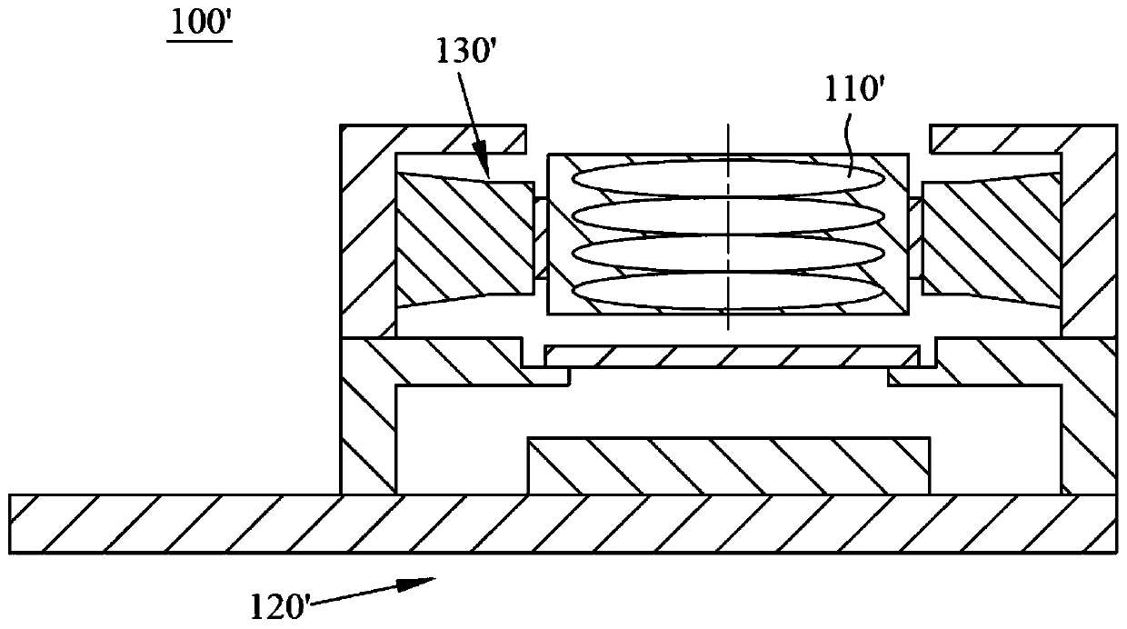
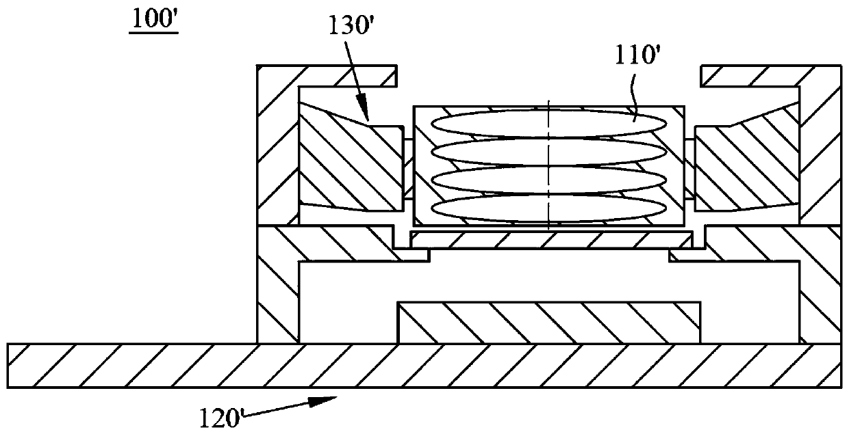
[0046] see figure 1 as well as figure 2 , the camera module 100' in the related art all changes the object distance and image distance of the camera module 100' by moving the lens group 110', and thereby realizes zooming. Depend on Figure 1 to Figure 2 , the lens group 110' moves away from the photosensitive component 120', the object distance u of the camera module 100' decreases, and the image distance v increases. According to the principle of optical imaging, the focal length f of the camera module 100' satisfies the following relationship Formula: 1 / f=1 / u+1 / v, wh...


PUM


Abstract

The invention discloses a camera module and electronic equipment. The camera module comprises: at least one lens; a light sensing assembly used for sensing light passing through the lens; and a driving device which can drive the light sensing assembly to move in the direction close to or away from the lens so as to adjust the focal length of the camera module. The driving device capable of drivingthe light sensing assembly to move is arranged in the camera module, the distance between the light sensing assembly and the lens is changed through movement of the light sensing assembly, and the zooming function of the camera module can be achieved. Since the weight of the light sensing assembly is far less than that of the lens, the requirement on the driving force of the driving device is low. Under the same condition, the moving efficiency of the light sensing assembly is high, and rapid zooming is convenient to achieve. Furthermore, as the lens is immobile, the view field opening of thecamera module can be kept in a small size, the normal imaging requirement can be met, the occupied space in the electronic equipment is small, and the arrangement, design and installation cost of other parts or assemblies is low.

Description

technical field [0001] The present application relates to the field of optical components, in particular to a camera module and electronic equipment. Background technique [0002] With the development of science and technology and the continuous improvement of people's economic level, various electronic devices are flooding people's lives. Among them, portable electronic devices with the characteristics of miniaturization and light weight are gradually favored by more and more people. Therefore, the camera modules used in them also need to realize miniaturization and light weight simultaneously. [0003] However, the electronic equipment in the related art realizes the zoom function through the movement of the lens group in the camera module. Its disadvantage is that the weight of the lens group is relatively large, and the power required to move the lens group is large, which requires high power devices and is not conducive to realizing fast zooming. Contents of the inve...

Claims


Application Information

Patent Timeline
IPC IPC(8): H04N5/225H04N5/232
CPCH04N23/54H04N23/57H04N23/55H04N23/67
Inventor 陈伟
Owner GUANGDONG OPPO MOBILE TELECOMM CORP LTD
Learn More