
System and method for realizing high-efficiency removal of fine particles in high-temperature gas through electrofiltration coupling

A technology for fine particulate matter and high temperature gas, which is applied in the field of systems for efficient removal of fine particulate matter in high temperature gas by coupling with electric filtration, which can solve the problems of limited temperature application range and achieve the effect of low power consumption and low gas consumption.

Pending Publication Date: 2020-07-14
ZHEJIANG UNIV
View PDF2 Cites 5 Cited by
  • Summary
  • Abstract
  • Description
  • Claims
  • Application Information

AI Technical Summary

Problems solved by technology

However, this technology has the following disadvantages: it is only suitable for dust removal of highly acidic gas with an acid dew point lower than 170 °C, the continuous temperature resistance limit of the valve used in the injection system is only 200 °C, and the temperature application range is limited
But it also has certain shortcomings: the filter cartridge can only operate at a temperature of 170°C for a long time, and the instantaneous temperature is 190°C

Method used


Image

  • System and method for realizing high-efficiency removal of fine particles in high-temperature gas through electrofiltration coupling
  • System and method for realizing high-efficiency removal of fine particles in high-temperature gas through electrofiltration coupling
  • System and method for realizing high-efficiency removal of fine particles in high-temperature gas through electrofiltration coupling

Examples


Embodiment Construction

[0050] The technical solution of the present invention will be further specifically described below through examples, and these examples are done to illustrate the present invention, not to limit the present invention. Based on the embodiments in this application, all other embodiments obtained by persons of ordinary skill in the art without making creative efforts belong to the scope of protection of this application.

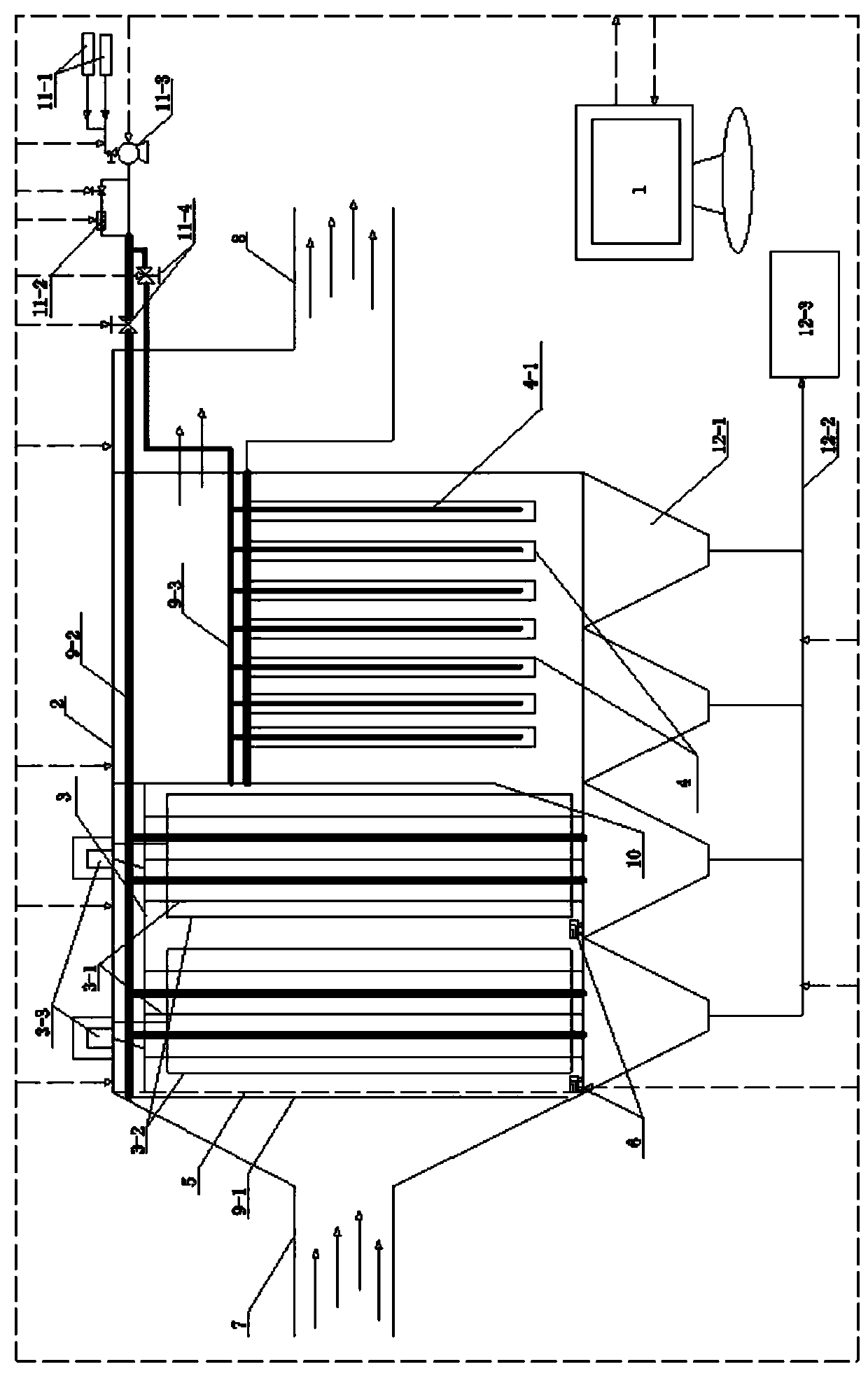
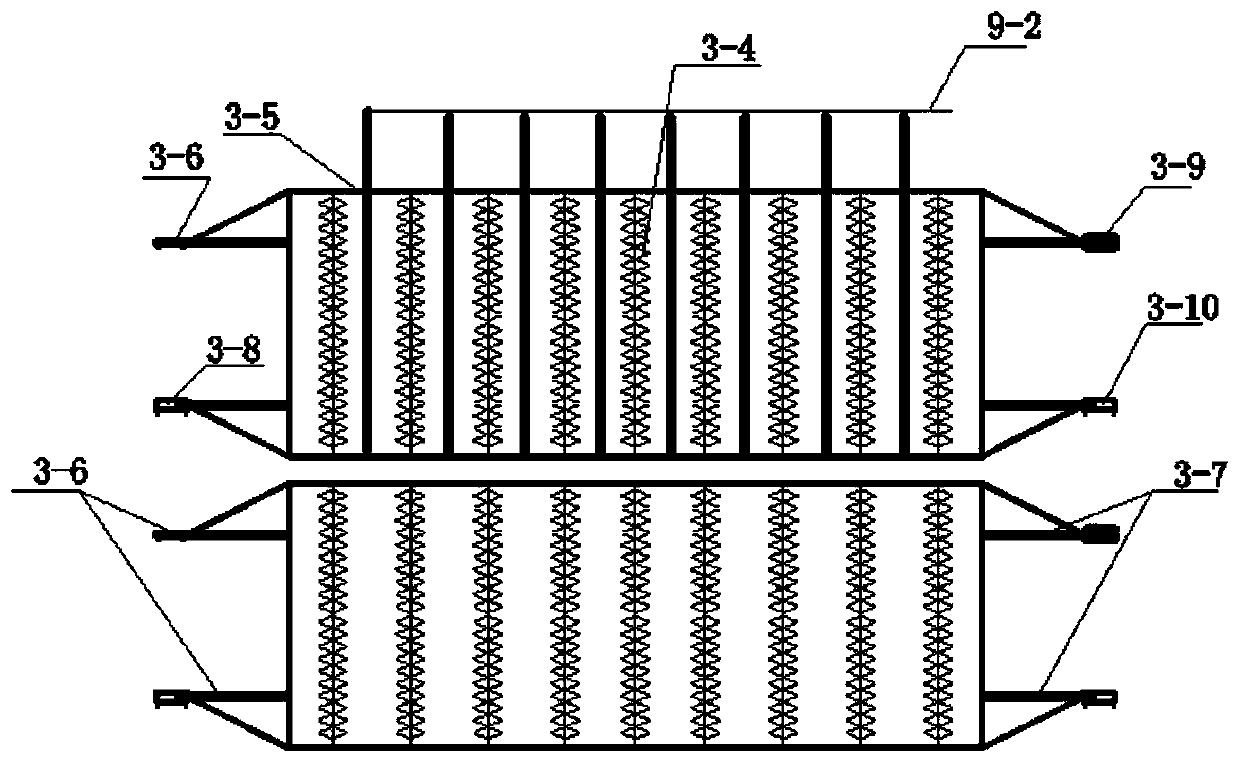
[0051] refer to Figure 1~6 , a system for efficiently removing fine particles in high-temperature gas through electric filtration coupling, the system includes an intelligent control device 1, a filter body 2, a discharge dust removal device 3, a filter dust removal device 4, a rectification device 5, and a tubular dust removal device device, rapping dust removal device 6, hot air device and ash conveying device, the discharge dust removal device 3, filter dust removal device 4, rectification device 5, pipe type dust removal device, and rapping dust removal d...


PUM

PropertyMeasurementUnit
particle diameteraaaaaaaaaa
pore sizeaaaaaaaaaa
lengthaaaaaaaaaa

Abstract

The invention relates to a system and method for realizing the high-efficiency removal of fine particles in high-temperature gas through electrofiltration coupling. The system comprises an intelligentcontrol device, a filter body, a discharge dust removal device, a filtering dust removal device, a rectifying device, a tubular ash removal device, a vibrating ash removal device, a hot air device and an ash conveying device; the intelligent control device collects, processes and feeds back all real-time monitoring data of the whole system. According to the system and method of the invention, anelectrofiltration coupled high-temperature flue gas dust removal system formed by combining the three devices, namely, the intelligent control device, the discharge dust removal device and the filtering dust removal device, the rectifying device and the tubular ash removal device are adopted; the advantages of each device technology are fully utilized; the restriction of flue gas conditions (temperature, components, physicochemical properties and the like) and smoke dust conditions on the dust removal performance of the dust removal device is effectively solved; the operation parameters of thehigh-temperature dust removal system are adjusted in real time by intelligently optimizing and regulating a key parameter model; and the purposes of energy conservation, consumption reduction and emission reduction are achieved.

Description

technical field [0001] The invention belongs to the technical field of air pollutant control, and specifically relates to a system and method for realizing high-efficiency removal of fine particles in high-temperature gas through electric filter coupling. Background technique [0002] my country's flue gas dust removal technologies mainly include cyclone dust removal, electrostatic dust removal, bag dust removal, and wet electrostatic dust removal processes. The application scenarios are limited by temperature conditions, and the general working temperature is a medium and low temperature environment below 200 °C. However, in the field of technological development in industries such as iron and steel, metallurgy, and building materials, there is a problem of particle capture under high temperature conditions. As a commonly used flue gas dust removal equipment, electrostatic precipitator has the advantages of high dust removal efficiency, low system resistance, low operating ...

Claims


Application Information

Patent Timeline
Patent Type & Authority Applications(China)
IPC IPC(8): B03C3/017B01D46/24B01D39/20B03C3/04B03C3/80B03C3/76
CPCB01D39/2017B01D39/2027B01D46/24B01D2239/0208B01D2239/0216B03C3/017B03C3/04B03C3/76B03C3/80
Inventor 高翔郑成航苏秋凤吴卫红张涌新周灿翁卫国王丁振姚龙超杨洋岑可法
Owner ZHEJIANG UNIV
Learn More