Spray pipe

A nozzle and pipe body technology, applied in the field of nozzles, can solve the problems of waste of manpower, slow discharge of nozzles, etc., and achieve the effects of improving production efficiency, short discharge time, and tight sealing

Pending Publication Date: 2020-07-14
阳光硅谷电子科技有限公司
View PDF0 Cites 1 Cited by
  • Summary
  • Abstract
  • Description
  • Claims
  • Application Information

AI Technical Summary

Problems solved by technology

[0003] In view of this, the present invention provides a nozzle to solve the problem of slow discharge and waste of manpower from the cutting fluid nozzle of the photovoltaic slicer

Method used


Image

  • Spray pipe
  • Spray pipe
  • Spray pipe

Examples


Embodiment Construction

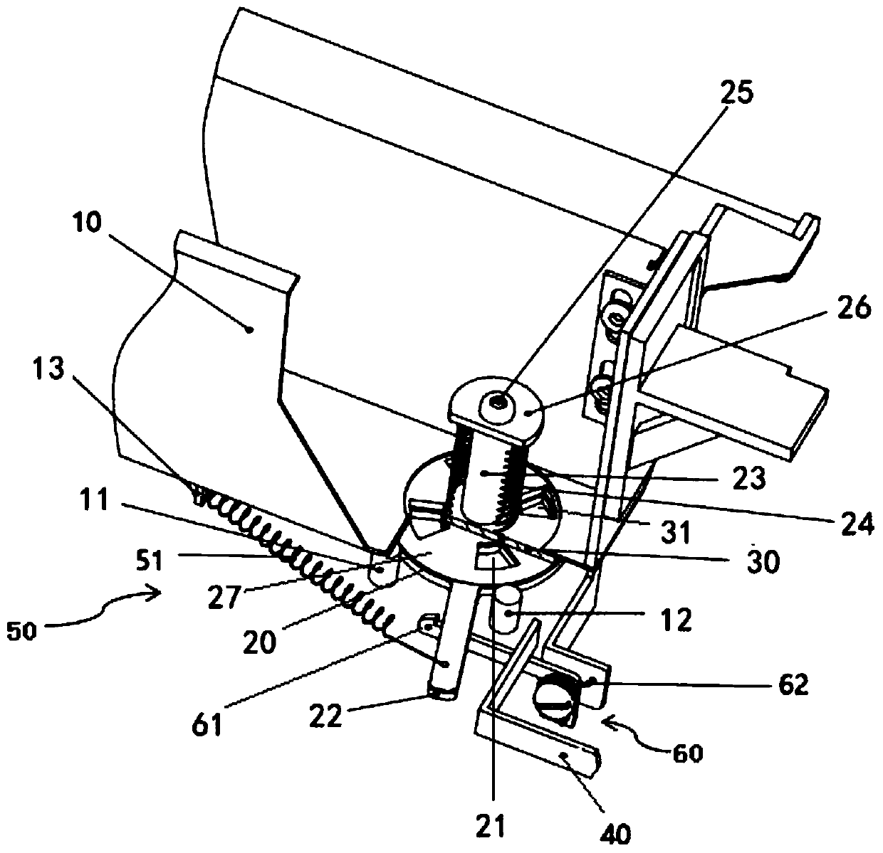
[0037] The nozzle according to the embodiment of the first aspect of the present invention will be described in detail below with reference to the accompanying drawings.

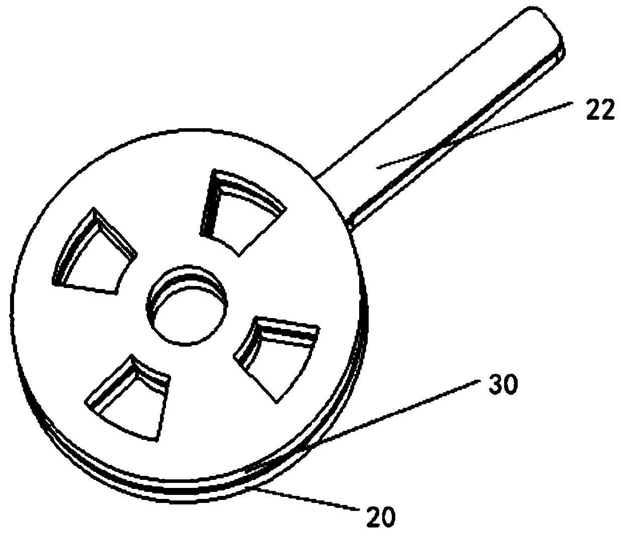
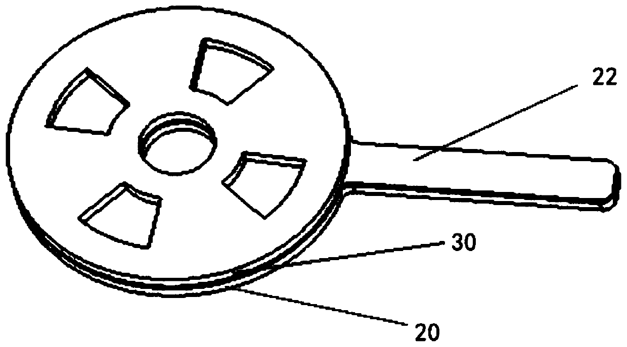
[0038] It should be noted that, in the embodiment of the present application, a through hole can be directly provided at the bottom of the pipe body, or a fixed valve plate can be provided on the pipe body, and the fixed valve plate is installed in the installation hole of the pipe body, and The fixed valve plate is circumferentially sealingly connected with the mounting hole to prevent the liquid in the pipe from flowing out through the mounting hole, and the fixed valve plate is provided with a second valve hole. Wherein, the through hole and the second valve hole are two completely consistent holes, for example, the size, shape, quantity and spacing between the holes are completely consistent, so that the through hole and the second valve hole can be connected with the rotary valve plate. Cooperate with t...


PUM


Abstract

The invention provides a spray pipe which comprises a pipe body and a rotary valve plate. Through holes are formed in the bottom of the pipe body, or installation holes are formed in the bottom of thepipe body, fixed valve plates are arranged in the installation holes, the fixed valve plates are connected with the installation holes in a circumferential sealing mode, and second valve holes are formed in the fixed valve plates, wherein the through holes are consistent with the second valve holes in shape, size and number; and the rotary valve plate is arranged on the outer side of the pipe body and is rotationally connected with the bottom of the pipe body in a sealed mode, the rotary valve plate is provided with first valve holes corresponding to the through holes and a wrench protrudingout of the outer edge of the rotary valve plate, and when the rotary valve plate rotates relative to the bottom of the pipe body, the through holes and the first valve holes are overlapped and form anopen hole for circulating liquid, or the through holes and the first valve holes are staggered and sealed. According to the spray pipe in the embodiment, the liquid discharge flow cross-sectional area can be increased during liquid discharge of a photovoltaic slicer, and the liquid discharge time can be shortened.

Description

technical field [0001] The invention relates to a nozzle, in particular to a cutting fluid nozzle applied to a photovoltaic slicer. Background technique [0002] The cutting fluid nozzle of the photovoltaic slicer supplies cutting coolant during the process of cutting silicon rods. After each cutting is completed, it needs to be drained and then disassembled. Nozzle. Existing cutting fluid nozzle generally adopts rubber ball installed under the spring rod end, the bottom is in contact with the round hole of cutting fluid nozzle to seal, the rubber ball is concentric with the hole, and the pull rod is positioned through two orifice plates on the cutting fluid nozzle. After the silicon rod is cut, when it is necessary to drain the liquid, manually pull up the upper hand-held ball of the pressure rod, the spring is compressed, and a gap is formed between the rubber ball and the round hole, and the remaining cutting fluid is discharged through the gap and the round hole. Durin...

Claims


Application Information

Patent Timeline
Patent Type & Authority Applications(China)
IPC IPC(8): B28D5/00B05B1/30
CPCB05B1/3026B28D5/0076
Inventor 周为贞荆新杰郭胜朝
Owner 阳光硅谷电子科技有限公司
Why Eureka
Try Eureka