
To-be-printed object mounting mechanism for ink-jet printer and mounting method

A technology of installation mechanism and installation method, which is applied to printing devices, typewriters, printing, etc., can solve the problems of affecting inkjet quality, installation, and failure to pass fixtures, etc., so as to facilitate software control of ink and ensure the quality of inkjet printing

Pending Publication Date: 2020-07-14
BEIJING MEIKEYI
View PDF2 Cites 1 Cited by
  • Summary
  • Abstract
  • Description
  • Claims
  • Application Information

AI Technical Summary

Problems solved by technology

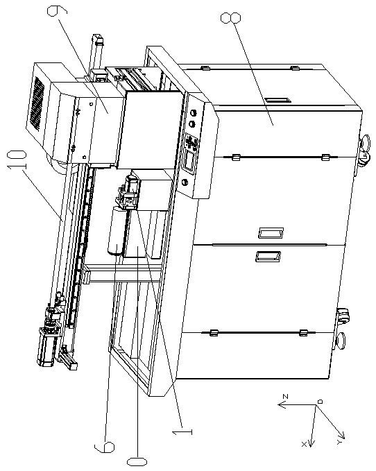
However, when printing small-diameter special objects, such as printing eyebrow pencils or other pen bodies and pen caps, since the driving mechanism 1 of the object to be printed has a certain peripheral size, after installation, the position of the highest busbar of the small-diameter object to be printed is not high enough. At the highest position of the part in the driving mechanism 1 of the object to be printed, it is still necessary to adjust the plane where the nozzle hole is located to be between 1-3 mm from the highest generatrix of the object to be printed before printing. Then, the upper end of the driving mechanism 1 of the object to be printed will be It is higher than the lower part of the nozzle, which leads to the collision of the nozzle. If the height of the printing carriage 9 is raised, the driving mechanism 1 of the object to be printed will not collide with the nozzle, but the distance between the plane where the nozzle hole of the nozzle is located and the position of the highest busbar of the object to be printed will be greater than Optimum printing distance, which affects inkjet quality
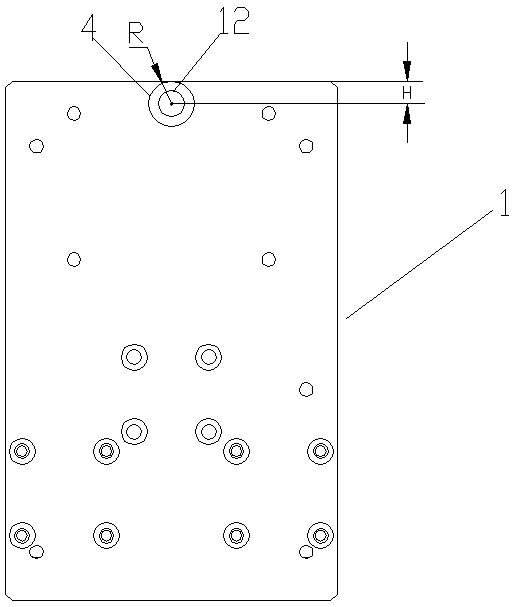
In addition, due to the structural design of the drive motor and the output shaft of the drive mechanism 1 of the object to be printed, the shaft diameter of the output shaft is larger than a certain size, and it cannot be installed by a jig when printing a small-diameter object to be printed.

Method used


Image

  • To-be-printed object mounting mechanism for ink-jet printer and mounting method
  • To-be-printed object mounting mechanism for ink-jet printer and mounting method
  • To-be-printed object mounting mechanism for ink-jet printer and mounting method

Examples


Embodiment 1

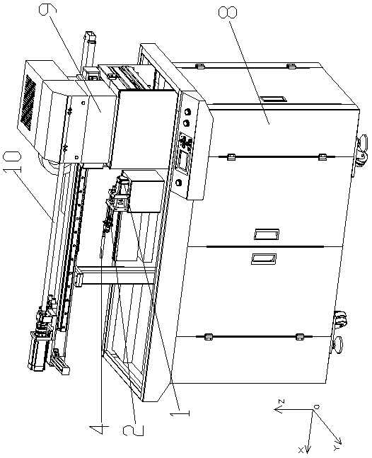
[0042] When it is necessary to print a small-diameter cylindrical object 4 to be printed, such as Figure 6 As shown, an object to be printed transfer mechanism 2 is connected to the outer end of the drive output shaft 12 of the object to be printed driving mechanism 1 , and an object to be printed 4 is connected to the output end of the object to be printed transfer mechanism 2 . The following is based on Figure 7-8 Describe in detail the transfer mechanism 2 of the object to be printed in this embodiment. The transfer mechanism 2 of the object to be printed includes a coupling 21, a connecting column 22, a first friction wheel 23, a first output shaft 24, a floating friction wheel 25, a floating shaft 26. The second friction wheel 27, the second output shaft 28 and the rear support seat 29. One end of the coupling 21 is connected to the drive output shaft 12 of the drive mechanism 1 of the object to be printed, and the other end is connected to the first drive of the transf...

Embodiment 2

[0046] When it is necessary to print a small-diameter object 4 to be printed, it can also be Figure 9 As shown, another object to be printed transfer mechanism 3 is connected to the outer end of the drive output shaft 12 of the object to be printed driving mechanism 1 , and the object to be printed 4 is connected to the output end of the object to be printed transfer mechanism 3 . The following is based on Figure 10-11 Describe in detail another transfer mechanism 3 for objects to be printed. The transfer mechanism 3 for objects to be printed includes a shaft coupling 21, a connecting column 22, an output shaft A31, a first gear 32, an output shaft B33 and a second gear 34. The shaft coupling One end of the device 21 is connected to the drive output shaft 12 of the drive mechanism 1 of the object to be printed, and the other end is connected to the output shaft A31 of the transfer mechanism 3 of the object to be printed. A first gear 32 is inserted on the output shaft A31, a...


PUM


Abstract

The invention discloses a to-be-printed object mounting mechanism for an ink-jet printer and a mounting method. The mounting mechanism comprises a driving part, a driving output part, a switching connection part, a switching transmission part and a switching output part, wherein the driving part sends out a rotary driving force, the driving output part is connected with the driving part to outputthe rotary driving force, the driving output part is connected with the switching transmission part through the switching connection part, the switching transmission part transmits the rotary drivingforce to the switching output part, and the switching output part is connected with a to-be-printed object. The application range of the ink-jet printer on to-be-printed objects (such as cylinders, cones or cylindrical / conical to-be-printed areas) with different sizes is expanded through the design of the switching connection part, the switching transmission part and the switching output part.

Description

technical field [0001] The invention relates to an object-to-be-printed installation mechanism and installation method for an inkjet printer, which is applied to a small-diameter cylinder, a cone, or an object to be printed with a cylinder / cone to be printed. Background technique [0002] The simplest method of printing exquisite patterns and characters on curved surfaces in the prior art is to print on a flat carrier, which is combined with the target curved surface. This method is time-consuming and laborious, and the final effect cannot be guaranteed. Chinese patent CN94115805.5 discloses a pattern transfer printing method, which is a printing method for transferring graphic lines on the curved surface of a molded product. Silk cotton paper is used as the transfer paper, and the pattern is printed with high-temperature sublimation air dyeing ink. Treatment, including cleaning, priming, thermal curing of the primer, applying induction resin and hardening, and then coating ...

Claims


Application Information

Patent Timeline
Patent Type & Authority Applications(China)
IPC IPC(8): B41J3/407B41J11/00B41J29/38
CPCB41J3/4073B41J11/00B41J29/38B41J3/40733
Inventor 张原张征宇
Owner BEIJING MEIKEYI
Learn More